A Realistic Lighting Rig by Andy Nicholas
This tutorial was written by Andy Nicholas who is an experienced freelance artist and programmer. Visit his site at www.andynicholas.com, where you can find more tutorials like this one.
This tutorial will show you how to create a lighting rig that will simulate daytime lighting conditions. Most importantly, it will allow you to easily adjust the rig so you can reuse the rig in many different scenes.
With support for lighting based on HDRI images and radiosity techniques, the need to create this sort of lighting rig is reduced. But it is still a useful trick to pull out of the bag when rendering times need to be reduced.
Luxigons
A much overlooked feature of Lightwave is the ability to create lights based on polygons created in Modeller. This is invaluable as it allows us to create our lighting rig with as many lights as we want.
To start, create a single polygon centered at ( x = 0 , y = 0 , z = 1m ), and make an array (using the radial option) about the y axis by the number of lights you wish to have in your rig (I’ll be using 16 to keep it simple for this tutorial, but you’ll probably want to use a higher number to improve shadow quality).
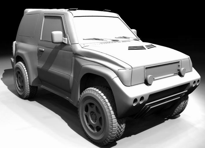
This lighting set-up was adequate for my Mitsubishi composite (see the movie gallery), but for more realism, you might want to use the polygons from a tesselated sphere.
Now select all the polygons and use the “Add Luxigons” command (which can usually be found in the Construct>>Additional menu). Don’t worry about the options here, just click on OK.
Now you’ve made your Luxigons (how easy was that huh!), save your object as “Luxigons.lwo” and start up Layout. This object is available for download with the finished rig at the end of this tutorial.
On the next page, I’ll show you how to convert your Luxigons and start building your rig.
In Layout, clear the scene and create two null objects at the world origin called “LightRigTarget” and “LightRigParent”.
Now load up the “Luxigons.lwo” object you created on the last page, and run the “Convert Luxigons” plugin which can be found in the Layout>>Plug-ins>>Generic Plug-ins menu. In the dialog box that appears, call the new lights “SkyLight”.
Delete the first original light (called “Light”) and also the Luxigons object (without clearing it’s decendents). Also, you must make sure you rename “SkyLight(1)” to “ControlSkyLight“, as otherwise, expressions will have difficulty in finding the object after a Load From Scene.
Now comes the fun stuff!
Multiple object expression assignment
Open up the Spreadsheet and change the property bank to “Light Properties: Basic”. Click on ControlSkyLight’s intensity entry and then shift click on SkyLight(15)’s intensity to highlight them all. Now click on the little box with the “E” in it and click “yes” to create intensity envelopes for all the lights. Repeat this process for the color property of the lights.
Still in Spreadsheet click on the name entry for ControlSkyLight, shift click on the name entry for SkyLight(15), and then double click anywhere in the highlighted area. This should select all the lights in the Layout viewport.
Close Spreadsheet and open the Graph Editor with all the lights still selected. Use Selection>>Get Layout Selected at the top of the Graph Editor window. Now from the same menu, select “Filter Curves” and enter:
*.Intensity
This will get rid of all the channels we don’t want to see. Use Channels>>Create Favourite Set to save this set as “Rig Intensity”. Repeat this process (starting from “Get Layout Selected” from the Selection menu) and create the following sets using these filters:
Channel Set Name Filter
Rig Red *.Color.R
Rig Green *.Color.G
Rig Blue *.Color.B
On the next page, we’ll add expressions to these channels.
So far we have created a set of lights, and created envelopes for intensity and color for each of them. We’ll now add expressions to drive the envelopes.
In graph editor, select the previously saved “Rig Intensity” channel bank to load the intensity channels for all the lights. Now select the Expression tab underneath the graph window, and click “New”. Enter “Intensity Follow” for the name, and delete the contents of the “Value” box.
Click on the “ControlSkyLight.Intensity” channel, and use the right mouse button menu to select the option “Append to Expression”. Now select all the channels by using the left mouse button and shift key, apart from “ControlSkyLight.Intensity”, and click “Apply” to set this expression for all the lights apart from ControlSkyLight.
Repeat this process for the other channel banks that we saved earlier, calling the expressions “Red Follow”, “Green Follow”, and “Blue Follow”. Remember to click “New” before entering the name for the new expression. If you mistakenly try to apply any of the expressions to ControlSkyLight, Lightwave will refuse, telling you that it has detected a loop in the expression.
You should end up with the graph editor looking something like this:
Setting Parent and Target
Go back into Spreadsheet, and change the property bank to “Motion Options: General”. Click on ControlSkyLight’s entry for “Parent” and shift click on SkyLight(15)’s entry.
By now selecting “LightRigParent” for any one of the lights by clicking on the small black arrow in the selected entry, it will also set the Parent property for the other lights as well. Set the Target property for all the lights to “LightRigTarget” using this method.
While we’re here, change the property bank to “Light Properties: Basic” and for all 16 lights set the Light Type to “Spotlight”. Also, set the property bank to “Light Properties: Shadow” to change the Shadow Type to “Shadow Map”.
As a final touch it is usually a good idea to parent the “LightRigTarget” null object to the “LightRigParent” unless you want the lights to track an object. Also, if you wish, you can set up expressions for cone angle, and soft edge angle in a similar way.
That’s it, finished! The next page shows how to get the most out of this setup.
A great idea to make everything a bit more user-friendly is to set up a bank of sliders to control the main parameters of ControlSkyLight.
To do this, use the Generic plug-in “Add Slider Bank”, and select the appropriate channels of ControlSkyLight to use as sliders. By clicking on the Sliders tool underneath Move, Rotate, Size, etc., you can move, resize, and adjust the sliders on the panel you just created.

The final lighting rig with sliders
Here’s an example of the Mitsubishi model (156,072 triangles) lit by this rig
These are four examples of using 40 lights created by luxigons from a tesselated sphere
For comparison, I rendered a version with full radiosity, and it took two seconds longer (see below) than the raytraced motion blur rig. So by using the rig, you get near radiosity quality with the added bonus of motion blur! Admittedly the shadow of the car is somewhat lacking, but for my Mitsubishi composite I did a seperate shadow pass, so this wasn’t a problem.
A great way to use this lighting rig, is to use it as a realistic alternative to setting an Ambient value. By using a fewer number of lights and combining them with one strong key light, the lighting rig acts like a fill-in light, and it can give that required extra dose of realism. It also hides many of the problems with shadows that are visible in the above images.
This was the final method of lighting for the Mitsubishi composite animation. While not a perfect lighting model, it gets the job well, and done fast – ideal for those tight deadlines.

Final lighting
You can download both lighting rigs and the luxigon models below:
Download: Tutorial01.zip (8.74 Kb)
This tutorial was written by Andy Nicholas who is an experienced freelance artist and programmer. Visit his site at www.andynicholas.com, where you can find more tutorials like this one.


