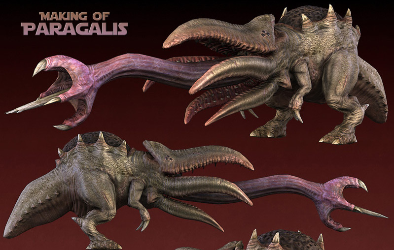
Making of Paragalis
Introduction:
This tutorial will cover my personal workflow for 3d modeling, 3d sculpting, retopo / optimizing, UV’s, normal map generation, light map generation, and texturing.
The Creature Summary:
Paragalis is literally a walking parasite that’s approximately the size of a large dog from tentacle tip to tale. The creature is an ambush predator who catches its prey with a tongue that can extend to twice the size of its body. Paragalis’s tentacle like mouth contains rows of teeth for gripping its prey, with a barb at the end its tongue that injects toxic venom! Once the prey has been caught its then quickly digested with its remains excreted from the creatures back hump in a gassy form! “I’d suggest that if you were to run into this thing to run the other way, quickly!”
The Specs: Lowpoly model / 7,000 triangles, Textures / 2024×2024 / diffuse, spec, normal
Tools: 3ds max 8 / 9, Photoshop, Mudbox, Zbrush 3.1, Crazybump, Polyboost
Step One: From concept to model
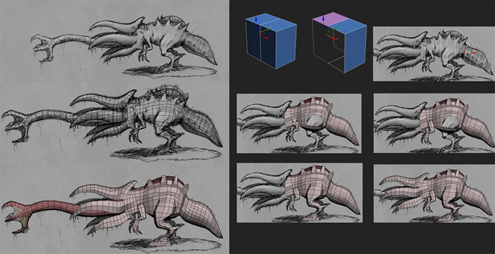
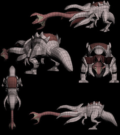
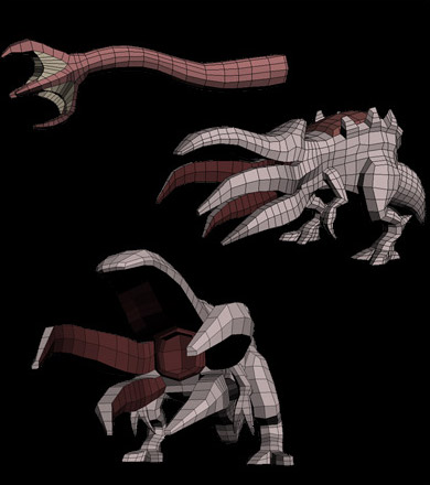
Once I have the design of the creature illustrated I then proceeded to the modeling phase. I find it helpful when making a symmetrical creature to at least have some sort of concept or rough outline to work from. This makes things easier on the modeling end and cuts out the guesswork when trying to nail the profile. I used a simple box modeling technique to quickly rough out the base mesh, just remember that I wasn’t going for any high-level detail and only focused on the broad strokes. This is important to remember since the model will change to some degree in the sculpting stage. When modeling the base mesh I try to keep in mind how much detail will be required in certain parts of the model, for instance I know that the tongue, tale and tentacles will need a good amount of detail. I also use this level of thinking when I work on characters as well, hence extra edge loops in the head, hands, etc.
Anyways as you can see from the images below I simply extruded a bunch of edges and faces in 3dsmax “editable poly mode”. I switched over to the perspective viewport once I was satisfied with the profile and began roughing out the form and proportions making sure the design held up in 3d. Since I didn’t draw a front sketch of the creature I had to use a bit of imagination on how wide it would look. I usually judge width by heads but I had to use its tail and a pig’s body instead due to the creature’s unusual design. As an artist it’s always good to reference actual creatures, people, places and things when making judgment calls on forms and proportions’, having this extra tool work wonders. Anyway the total modeling time was around an hour and a half and it’s completely made up of quads.
Step Two: Separate Elements
When it comes to creating a base mesh it’s always good to think two steps ahead so you don’t run into any issues later on down the road! This is why I created the tongue separately; doing so will free me up in the sculpting stage too not only hide that part of the mesh easily but also subdivide the hell out of it for more detail. I can get away with this method since the tongue goes pretty far back in its mouth and doesn’t contain any obvious skin interaction.
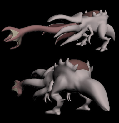
Step Three: Subdivide smooth Test
Once I’ve completed the base mesh I then run a few tests, mainly 3ds max “turbo smooth modifier”. As a rule of thumb I always make sure that my quad based models can withstand a turbo smooth. This is important since this’ll give me a heads up on how it’s going to smooth in either Mudbox or Zbrush, not only that but I can also look out for any weird pinching in obvious areas.
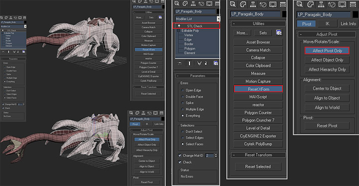
Step Four: Preparing for Export
After I finished checking the base mesh for any smoothing oddities it’s time to get it ready for export. I’m pretty paranoid about errors like double faces, multiple edges, holes, etc. Due to this I make sure to run 3dsmax “STL check modifier”, this will instantly highlight any errors my base mesh contains. Once the modifier has been run it’s time to “Reset Xform” which basically resets all transforms made to my base mesh. Last but not the least is setting up my pivots, I tend to center my pivots to the object and then adjust it to a comfortable position. The reason for this is so that both the pivots in my modeling app and sculpting app match up. I find this to be helpful when working with multiple elements, for example a space marine with lots of separate gear.
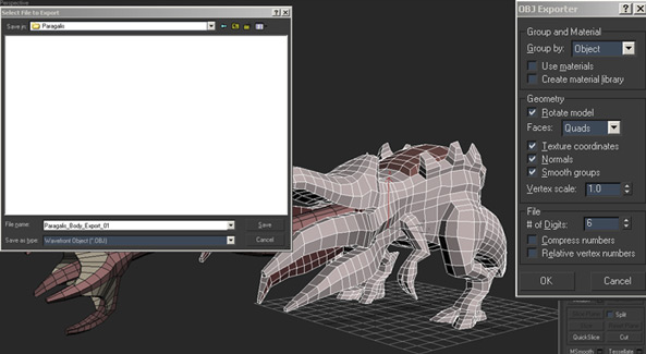
Step Five: Model Export
This step is pretty easy as you can see the settings that I used from the screen shot below.
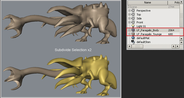
Step Six: Model Import
This is pretty self-explanatory much like the export step but I did want to highlight the fact that I name my separate elements! I think it’s a good habit to get into when dealing with multiple objects. Once both objects are in my sculpting app I then subd the mesh to a workable density level.
Step Seven: Creating the Reference sheet and Paint Over
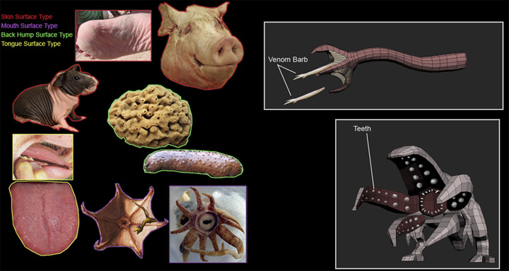
I find that it’s important to gather your reference materials even at this early stage and create what’s called a “Material callout sheet”. Generally this sheet is created before the texturing stage but comes in handy when you have to sculpt as well. I can’t stress this enough but it’s always good to be prepared and have some sort of reference handy! I see way to many artists pulling out detail from thin air without any real appreciation for the surface their trying to simulate. With that said, the sheet should have a healthy mix of photos and illustrations. While the reference sheet isn’t written in stone it’ll serve as an initial guide for you and or client, art director, etc. The last thing I wanted to address was the teeth; I kept them separate since they would just get in the way of my sculpting. Imagine trying to work up to nice level of detail in your sculpt while avoiding rows of little teeth along the way, it’s pretty annoying and it’s always best to leave small details like that off until the sculpt is near completion.
Step Eight: Creating the Digital Sculpt
Part One: Establishing the Detail Flow
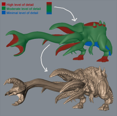
The first thing you need to do when creating a sculpture is to identify your detail flow. This means you should visually breakdown where certain details are going to be placed on the object and how intense they need to be. This is an important step to master since it’s easy to lose your way when sculpting! Personally I believe this approach and level of observation will result in a more focused effort and a better sculpt when all said and done. You can see from image below that I broke down what areas required what details and how they will be distributed throughout the model.
Minimal level of detail: This area should contain a subtle amount of surface detail corresponding to the surface and or material type. Usually this area is made up of broad sections on the sculpture and doesn’t contain much visual interest. In regards to Paragalis I made this area consist of stretched skin which at first glance may appear to be quite intense but will be pushed to the background once the model has been baked and textured.
Moderate level of detail: This area will make up most of the detail on the sculpture and will usually contain a broad sense of visual interest. As you can see from the image below, Paragalis is mostly made up of moderate detail, which contains general muscle, skin, and fat information.
High level of detail: These are the areas that should contain extreme levels of surface information. Usually these areas are kept to a minimum to increase their visual impact and presence. When it came to Paragalis, I focused the high level detail to the tentacle like a mouth, tongue tip, back hump, feet and parts of the top skin.
In closing all objects whether there are people, places, or things require different levels of detail, which can vary quite a bit since you can easily go from the modest to the extreme. The most important thing at the end of the day is to recognize what you’re making and how it’s going to be perceived by the viewer. Now what that means in terms of game art is to always have your creation readable at various distances without losing its purpose.
Part Two / Building on the Curve
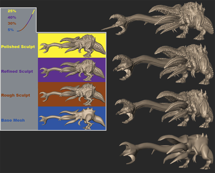
So now that I have a good idea on how to approach the model, it’s time for me to start sculpting out the forms. You can easily see that I move in steps from the images below.
Base Mesh: This is my imported mesh that I’ll look over and make slight changes to, usually I’ll only adjust the proportions and positioning on certain elements here.
Rough Sculpt: In this step I’ll quickly start applying the rough muscle mass making sure to only make broad strokes and staying away from any high level details. I encourage you when in this step to shy away from going into too high of a sub division level! Make sure to pick a moderately detailed subdivision level and work on it until you can only see the rough forms taking shape. The reason you want to do this is so that you can avoid obvious lumpiness, misshaped details, pinching, etc. When it came to Paragalis I went from the base mesh “body only” which was 2064 polygons to the third subdivision level, which was 33,024 polygons. It was at the third sub division level where I spent a good deal of time roughing out the sculpture.
Refined Sculpt: I subdivided the mesh two more times and proceeded to the next step once I was satisfied with the rough sculpture’s forms and level of detail. This is the step where I focused on pulling together the details such as muscle mass, skin, nails, fat, etc. It’s important to keep your energy and attention focused on working with the detail you have and making sure that it’s what you want before moving onto the next step.
Polished Sculpt: Now it’s time for me to add the finishing touches to the sculpture. This is where I add the teeth and focus on the little things like the skin, back hump, tongue, or anything else that will make the sculpt feel more alive.
Step Nine: Retopology / Optimizing the model
All right, now that I’m happy with my high poly mesh it’s time to convert into a low poly model, so where do I start? Well I have a few options available to me in this task and I’ll make sure to give a brief overview of each of them. Up until this point I’ve tried to stay software neutral but looks as though I have to get a bit specific in terms of the functions and workflow. From here on I’ll be going over a few features in both Zbrush 3.1 and 3ds max with Polyboost. So let’s start with option number one.
ZBrush 3.1 retopology workflow:
ZBrush as we know has a cool set of tools and one of them happens to be its ability to build new topology over an imported mesh! Below, the quick start guide pretty much shows how I get up and run when it comes to building new topology in ZBrush. Before I begin there are few things you need to know when you’re just starting out:
– When creating your low poly mesh you can deselect by clicking on the canvas, and when you want to select vertices just click on it.
– To delete a vertex hit “alt” and click on the vertices you want to get rid of.
– To create new edges just click on it, “preferably” in the center of the edge”.
– Make sure to hit “A” regularly preview what your retopologized model will look like.
– If you would like to have open holes in your retopologized mesh then set the “Max Strip length to 3 or 4.
– If you would like to move the vertices you created around, then go into move mode. The “Move” button is right next to the “Draw and Edit” buttons.
Once you’re done editing those vertices you can switch back to draw mode.
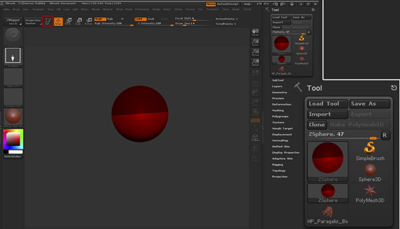
1. The first thing I have to do is to import my Mesh into ZBrush as a tool.
2. Once my mesh is loaded I select a zsphere and draw it on the canvas, after that I press the edit button.
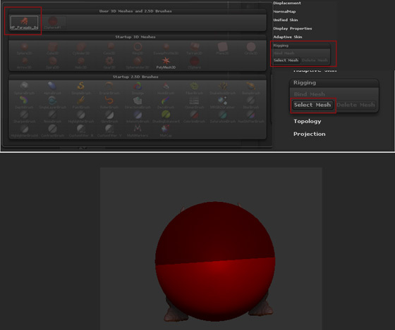
3. Then in the rigging tab I select the model that I want to retopologize. When that happens the tool momentarily shares the same space as the ZSphere.
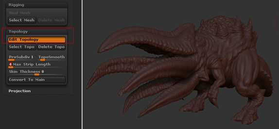
4. After that I click on the topology tab and Hit "Edit Topology". The mesh is the only thing on the canvas at this point and it turns brick red.
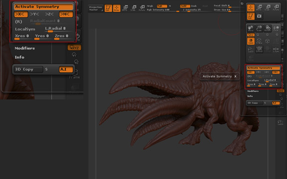
5. Then go into the Transform palette and turn on symmetry
6. When that’s done I click on the model to start adding new topology lines, creating and connecting vertices along the way.
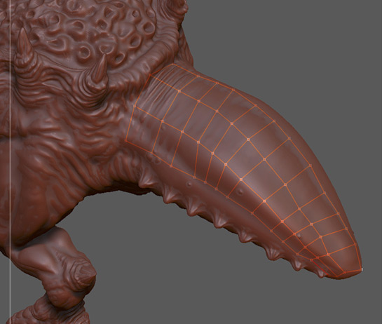
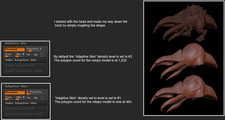
At this point I start creating the vertices that connects the topology lines. You can see from the image below how this works. I started with the head and made my way down the back by simply roughing out the shape. I try not to worry about edge flow and tight detail in the early going; I simply concentrate on all of the big forms. Once I have the new topology conformed to the mesh, I then begin to tweak the vertices and edges for better edge flow. You should always keep in mind that the new topology would be used for a low poly model, so try not to concern yourself with a perfect shrink-wrap! All you need is enough new geometry that you can modify in your 3d application. Another cool thing about Zbrush is Adaptive Skin, you can pretty much cycle through higher and lower subdivision levels by adjusting the slider. What this means is that you can comfortably build your new mesh at a higher subdivision level and reduce it on the fly when you’re ready. When the mesh is completed I simply hit the “A” button to look over my mesh, then I go to the tool palette and export the new geometry.
At this point I start creating the vertices that connects the topology lines. You can see from the image below how this works. I started with the head and made my way down the back by simply roughing out the shape. I try not to worry about edge flow and tight detail in the early going; I simply concentrate on all of the big forms. Once I have the new topology conformed to the mesh, I then begin to tweak the vertices and edges for better edge flow. You should always keep in mind that the new topology would be used for a low poly model, so try not to concern yourself with a perfect shrink-wrap! All you need is enough new geometry that you can modify in your 3d application. Another cool thing about Zbrush is Adaptive Skin, you can pretty much cycle through higher and lower subdivision levels by adjusting the slider. What this means is that you can comfortably build your new mesh at a higher subdivision level and reduce it on the fly when you’re ready. When the mesh is completed I simply hit the “A” button to look over my mesh, then I go to the tool palette and export the new geometry.
Well that’s it from the Zbrush aspect of things; I could have continued building out the new mesh by repeating most of the steps mentioned above. Instead I’m going to move into the 3ds max / Polyboost workflow and demonstrate a few of the tools features.
3ds Max / Polyboost retopology Workflow
Before going over this method I wanted to talk a bit about Polyboost. Polyboost is a max script that features a number of handy tools for modeling, texturing, UV mapping, transforming, selecting, etc. Unfortunately it’s not a free max script but I will tell you that I find it extremely valuable and have incorporated it into daily my workflow. That being said I highly recommend this to artists who want to get a little more mileage out of 3ds max! By the way you can view some of the additional Polyboost features on www.polyboost.com
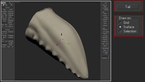
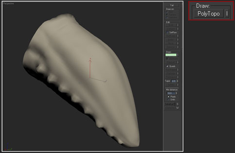
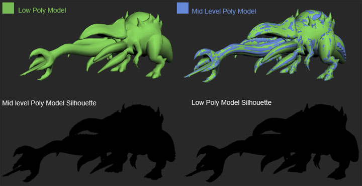
This is a brief overview on how I get started rebuilding topology in 3dsmax, which in turn will feel a bit like the Zbrush 3.1 workflow. Only now I’ll be working with a much lower triangle count source mesh. Once I was happy with the high poly mesh I proceeded to go down a few sub division levels and export it at a level 3ds max can handle, the midlevel mesh that was exported came in at 66,048 triangles. The cool thing is that the midlevel source mesh carries all of the silhouette detail needed for me to start building around. That being said you can see from the image below how the selected tools in Polyboost work. The main tool that I’ll be using is “PolyDraw”. Under PolyDraw are a number of sub tools that I’ll be using as well, mainly the “PolyTopo” brush and the “Build” tool. I selected the tale and hide the rest of the mesh so that you can see how the tools work.. Here are the steps involved:
1. I make sure to set my "Drawn on" to surface mode. The "Surface" mode allows me to select an object with the "Pick" button so that I can draw on the surface of that object.
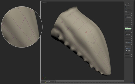
2. Next, I click on "PolyTopo". Polytopo is a topology brush that draws surface lines across your selected mesh. The Tool has a free form feel to it unlike ZBrush’s which tends to create a set of ridged interconnecting vertices.
3. At this point I start drawing on my mesh. I like to make sure to only draw on the surface area I can view comfortably, much like ZBrush Polyboost has a hard time figuring out certain angles.
4. When I want to view the mesh I just "Right Click", this deactivates the Polyboost tool set.
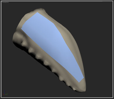
5. Then I continue retopologizing my new mesh around the tail by selecting the retopo mesh and going into vertex mode.
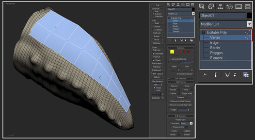
6. Then under "Edit" I select "Build" and start adding additional vertices. The vertices will automatically conform to mesh surface.
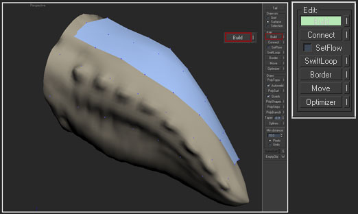
7. Now it’s time for me to connect the vertices to make new faces. I do so by Holding "Shift + Drag", this will automatically create faces in between the vertices filling in the gaps.
And that’s it, I simply rinse and repeat the process until the entire mesh is retopologized.
Modeling Application / Retopology workflow
So let’s say you don’t have access to Zbrush 3.1 or cool tools like Polyboost, what do you do? Well in this case you’ll have to shift your workflow to sheer brute force optimizations. This was a workflow that I often used before I got a hold of Zbrush and Polyboost, and to be honest I still use it every now and then. You simply have to export a subdivision level that conforms to the high poly silhouette and begin stripping away edges and faces. I know a number of artists who actually prefer this method and have become very proficient at it. This method takes quite a bit of patience and a mastery of your modeling tools!
There are a number of different tools like “Topogun, Blender, Nex, etc. that also do a good job of building new topology over your source mesh. I guess you’ll have to find out what works best for you and run with it!
Paragalis / Retopology / Optimizing the model:
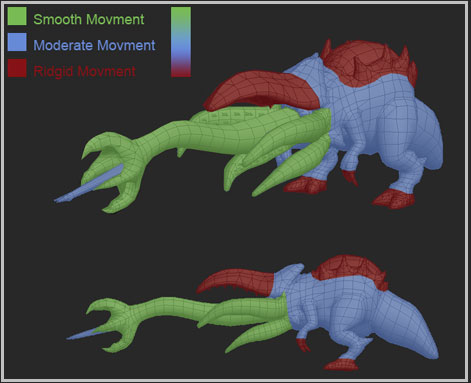
Defining edge loops:
So now that my mesh is almost done I want to highlight areas within the model that require most of the edge loops for posing and animation purposes. Now “I am not an animator” but I’ve worked with enough of them to know what they like and what they don’t. Looking at the image below you can see the areas that required the most edge loops for smoother movement. The tongue, lower tentacles, shoulders, knees, and ankles get an additional loop, or in the tongues case a bunch of them! Since this is a personal project I’m pretty much guessing on what areas require what based on past creature work experience. Had this model actually been created for a production I would have consulted with the animator to see what I could “get away” with in the modeling stage. With that said I’m pretty happy with the mesh as it is and will now move on to matching up the mid level poly and low poly meshes.
Paragalis / Retopology / Optimizing the model:
The Final Results:
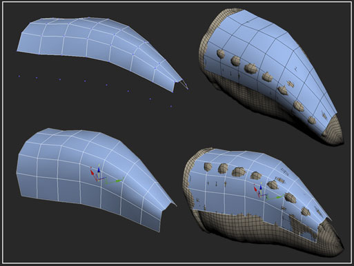
At this point I go over the mesh one more time, tweaking it here and there making any and all necessary adjustments. You can see from the images below how the low poly mesh matches up with the mid level poly mesh. Once I’m done with my tweaks I then weld all of the vertices and move onto the next step, which would be the UV’s.
Step Ten: Creating the UV’s
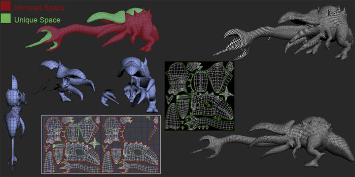
Now that my models completed and I can move onto creating the UV’s. Of course before I start cutting the mesh up, it’s important for me to identify what’s going to be mirrored and what’s going to be unique. This is an important step since the final texture is going to be 1024×1024 in size and every pixel counts! You can see from the image below how I broke down the parts of the mesh that have unique space and the parts that don’t. For the most part this creature is mostly symmetrical and I treated the UV’s as such with the exception of the top part of its head, hump back, inside tongue and poisonous barb. The reason I left those areas unique is so that I can add some interesting details within the texture work to break up the symmetry. When it comes to symmetrical creatures I try to have the areas you can’t view at the same time mirrored, and the areas you can view at the same time unique!
Now the last thing I want to touch on was the way in which I handled the UV chunks and mesh itself. When applying UV’s like this I usually delete the parts of the mesh that will be mirrored, and then I go ahead and work on the UV’s until it’s finished. Once the UV’s are done I select the parts of the mesh that are mirrored and clone that side of the mesh over to the other side. I then weld my vertices back into place when this is completed. I find this workflow to be much easier than doing UV’s for the whole mesh; it’s much more efficient and saves on the production time! With UV’s completed it’s time for me to arrange the UV chunks into the 0 to 1 UV space. I like to think of this step as one big jigsaw puzzle. With that said it’s always good to try and make use of every pixel and leave as little negative space as possible! You can see the final UV’s from the image below.
This is a “crucial” step in the creation process and should be handled with the utmost care. Most problems with, texture clarity, and normal map bakes can be traced directly back to the UV phase and is usually the culprit for many weird texture situations! Below is a short list of things to maintain when working with UV’s.
1. Always go for at least 95% distortion free textures. Having lots of distortion will result in blurry textures and bad normal map bakes.
2. Try and keep your UV chunks as vertical and horizontal as possible. This makes texturing / painting them easier, not to mention that it keeps your pixels aligned.
3. Make sure to maximize your UV space, keep the negative “black” areas to a minimum.
4. Keep the seams in places not easily seen by the viewer. Places like inner thighs, under arms, back of the neck, underbelly, etc. are good places to have seems.
5. Always try and add creative mirroring when possible to maximize your pixel resolution. Areas like hands, feet, neck, tail, wings, etc. are perfect candidates for this.
6. Always try and use large UV chunks and refrain from breaking your mesh up into lots of small pieces. This just creates more seems which will create more headaches!
7. Always apply a generous amount of pixel ratio to the places most seen by the viewer! For example the bottom of the creature’s feet didn’t receive the same pixel density, as its head or any other place of interest.
Step Eleven: Baking out Normal and Light maps
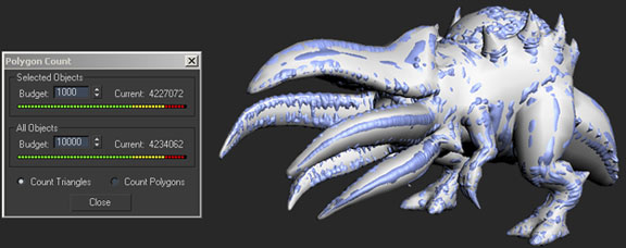
With the UV’s in place it’s time to get to one of the most important steps of the creation process, and that’s generating the normal and light maps! Now before I proceed with the workflow I want to highlight the fact that I’m running a PC with Windows XP64, 8gb of ram, Geforce 8800 GT 512mb, and a dual core 2.40ghz processor. The only reason that I’m highlighting this is due to the mesh sizes that I’m going to import into 3ds max. Currently I can comfortably import a model that’s roughly 5 million triangles in 3ds max 8 and around 6 million in 3ds max 9 without max crashing. With that said I would encourage you to do a few benchmark tests to see what you can work with on your own system! Okay so it’s time for the actual work flow.
Normal Map Generation
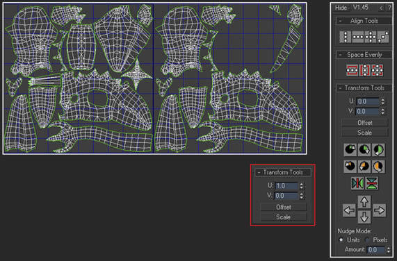
1. The first thing that I did was model UV’s and offset all of the mirrored UV chunks. I used "Chugnuts UV Tools" for this action and I highly recommend it to anyone using 3dsmax.
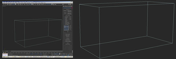
2. The next thing I did was hit "O" on the keyboard, this ensures that when I rotate the models all I can see is a bounding box!. This is a key since moving a dense mesh around your viewport can really slow down your system.
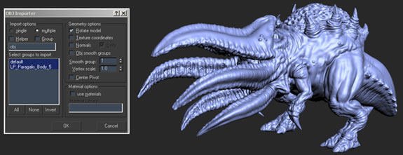
3. After that I proceed to import my high poly mesh, you can see the settings that I use from the image below.
4. My step next was to make sure both the low-poly mesh and high poly overlap properly.
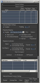
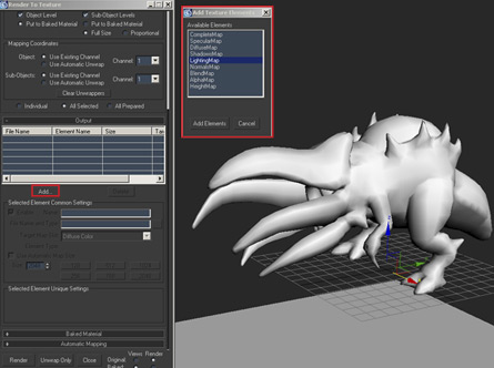
5. The next thing I did was hit "O" on the keyboard to bring up the "Render to Texture" dialog box.
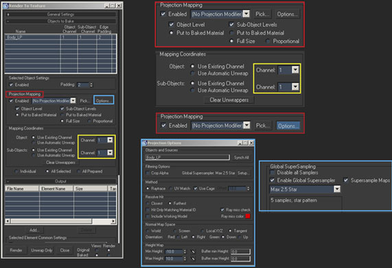
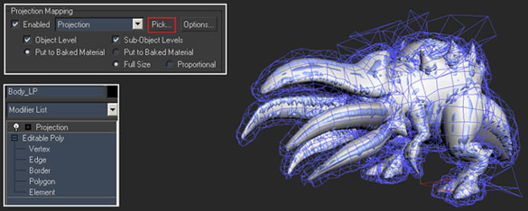
6. Once the dialog box came up I went ahead and adjusted some of the settings. For Instance I made sure that “Projection Mapping” was enabled, and it was using channel 1 for both the object and sub objects and that “Global Super Sampler” was enabled. By the way I use “Max 2.5 Star”. The last thing I did was make 3ds max was saving the file to my desired location and not the default (C:\Program files\Autodesk\3dsMax#\images)
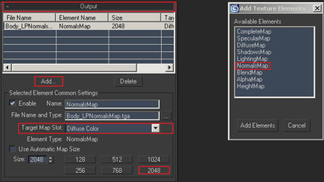
7. With the initial settings in place, I moved on to adding the elements necessary for the baking. I hit the “add” button underneath the “Output” rollout and selected “NormalsMap” from the available elements list. Once I did that I picked “Diffuse Color” from the target map slot. The next and last thing I did was select the texture map size that I want 3dsmax to bake; in this case I picked 2048×2048.
8. Now that all of my settings are in place I went ahead and hit the "Pick" button . The "Add" targets dialog box appeared and I selected the high poly target mesh, this applied a projection to my modifier stack. As you can see from the image below the cage for the projection is unadjusted and all over the place.
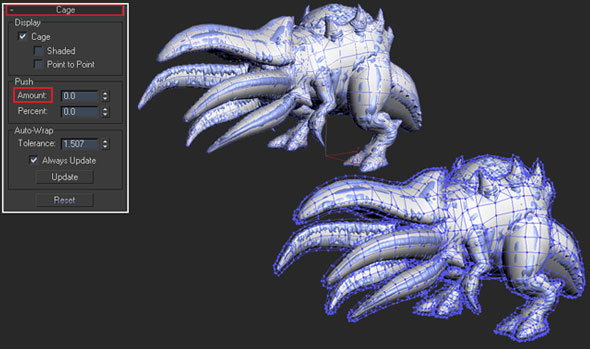
9. My next step was to go into the "Cage Rollout" and hit the reset button to get the things back in order. Now my cage was reset, I went ahead and pushed the amount to around 0.75
10. Now everything was in order, I hit the “Render” button on the Render to texture dialog box.
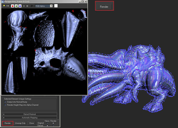
At this point I’m now going to go over my normal bake and investigate what needs adjusting. The reason is no matter how perfect your mesh and cage is, you will most likely have to make some small adjustments to the cage and in some cases the model after the first bake! So you can see from the image below what needed fixing to get rid of the obvious red spots. Now when I say “obvious red spots” I mean parts of the mesh where the cage is intersecting with the low poly mesh geometry. Keep in mind that there are other instances where you’ll have red spots no matter what you do, this is caused by overlapping or intersecting geo, missing faces, missing UV chunks, etc. In Paragalis’s case most of the red spots were due to the cage not being out far enough in certain areas. The only exceptions were the armpit and inner thigh seem. That being the case and I went in and adjusted those areas, you can see an example of one of the trouble spots in the image below.
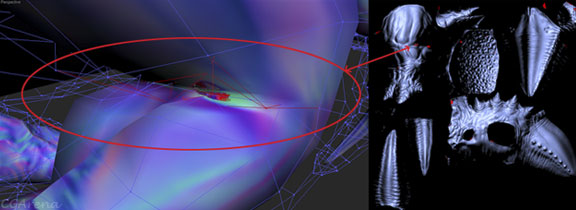
“Special note”, you can hide the high poly mesh when making adjustments to the low poly mesh. The changes you make will still apply once your finished and you’ve unhidden the high poly mesh!” Now that I’ve fixed my trouble spots I did another render. You can see from the image that I was able to get a cleaner normal map from the second bake, yay! Now that the bake has turned out successful I went ahead and repeated the process for the tongue in a separate 3dsmax file. That being the case you should always try “if you can help it” to create your models in separate elements. This way you can bake out the elements separately from higher resolution source meshes!
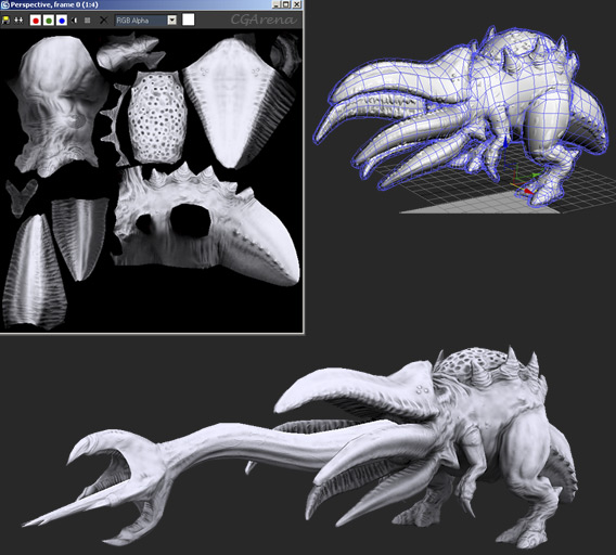
In closing, you can see that by following these easy steps that I was able to get a solid normal map! The overall keys to achieving these results comes from having a clean low poly model, clean high poly model, and solid “non-overlapped” UV’s, all in all there’s no magic bullet to this and it takes a bit of practice and patience. With that said you can see the normal map results below when compared to the high poly version.
Light Map Generation
All right, now I have the normals baked out and I can move into baking out the light map! This step actually benefits from all of the hard work setup during the normal map bake. While still having my normal map file open I went ahead and renamed the file “Paragalis light map bake”. Once that was done I simply followed these steps:
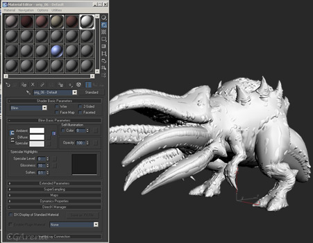
1. I opened the material editor and created a solid white material. The next thing I did was apply the material to both the high poly and low poly mesh.
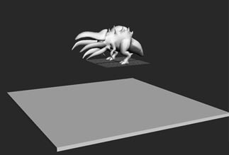
2. After that I created a white floor “box” underneath the grid and move it a few units below the model. Having the floor in the scene allows for shadows to be baked into the underbelly of the mesh. The closer the floor is to the mesh the darker the shadows and vice versa for lighter shadows. “Special Note” ordinarily it’s good to have some nice shadows underneath the mesh to create depth but it’s not appropriate to have the shadows appear completely black either. The same could be said for any and all intersecting geometry.
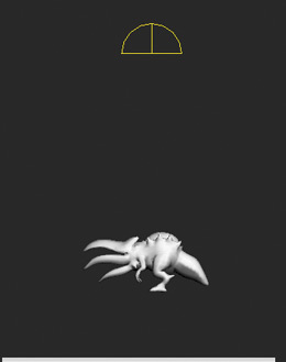
3. Then I went ahead and added a skylight to my scene and raised it above my mesh.
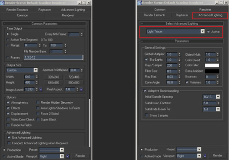
4. Then I hit the “F10” key to bring up the “Render Scene” dialog box. I then selected “Light tracer” under the “Advanced Lighting” tab. As a side note there are a number of cool things you can do under “General Settings” and “Adaptive Under sampling” for some nice bake variants! With that said I highly recommend investigating what each setting does.
5. The next thing I did was hit “0” on the keyboard to bring up the “Render to Texture” dialog box. From here I pretty much followed the same steps as in normal map workflow with the exception of picking “Lighting Map” from the “Add texture Elements” dialog box instead of Normals Map.
6. With my cage still intact from the normal map session, I went ahead and did the actual light map render. You can see the results of the bake from the image below.
“Special Note” You can also create a light map based off on the low poly geometry instead of the high poly source simply by leaving the “Projection Mapping” / Enabled box unchecked. The reason you may want to do this is to create another light map connecting the shadows to multiple elements.Case and point would be the creature’s tongue and body. If you look closely at the image above you can see that the tongue feels disconnected to where the rear of the tongue connects to the body. In this case I generated a second light map, which I later blended with the baked light map. You’ll be able to see the results of this in the next step.
Well that’s it from the baking side of things; this is pretty much my work flow for generating both the normal and light maps within 3ds max.


About The Author
You might be interested in