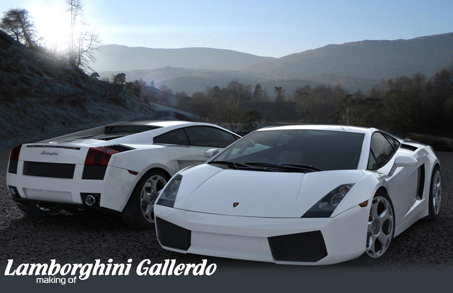
The Making of Lamborghini Gallerdo

This image was created for a personal project to brush up on my high-end skills, having only been working on lower poly game art for the past few years. The mesh is approximately 1.5 million polygons and Brazil r/s was used to render out the model.


March 22, 2006 | Stryker


This image was created for a personal project to brush up on my high-end skills, having only been working on lower poly game art for the past few years. The mesh is approximately 1.5 million polygons and Brazil r/s was used to render out the model. The back ground and the environment map is a photo I took whilst on a trip to the Lake district. I thought it would be nice to try and comp the car into one of these photos and here are the results. The PC used to do the work was an AMD 3200+ with 1GB of Ram

The beginning This is were this project began using top, side and front profiles mapped onto a box, the box has had its normals flipped and unused faces removed. One of the most important things when setting up your guide is to ensure that your blue print images have equal widths and height, and the box you use to map them onto is at the same proportion to the blue print images. If you get this wrong your car will be out of proportion!! You must also be aware that most blue print data isn’t 100% correct and should be used as a starting point for your work.


A good library of photographic reference is essential for creating detailed work, although you can’t really use any top side or front shots to trace profiles due to perspective ect they will give u a true interpretation of your subject. It is important to develop skills in reading the shape of an object from a photo, reflections on the surface is a very good way of understanding its shape as well as the subtle shadows cast on the shape. Once again there are issues with this, advertising art work is very useful but some images have been enhanced or altered slightly via photo editing and aren’t always easy to read, the best sort of photo ref are standard shots from owners or enthusiasts. In total I collected over 40 images using google and although it takes time it will help make a more accurate model. Below are some shots of the ref and a screen grab showing reference of the rear car open while the rear of the car is being worked on.


The first image shows the side view of the car under construction, it is important to note that although the doors are not yet separate from the body there is a set of edges that follow the profile of the shut lines. This makes it quicker and easier to separate the door at a later stage, it is an essential part of the construction process to make the side of the car as one object initially as it ensures the door profile will flow correctly with the rest of surrounding profile.

The second image shows a small increment of the construction using the extrude edge function, more geometry is created around the door and wheel arch area. In the second image the geometry around the rear wheel arch is being cleaned up before the separate wheel arch geometry profile is added to the main body shape. (black arches)


Using instanced arrays
Building up the wheels using instanced arrays means that what ever work you do on any of the individual wheel objetcs is repeated on all the other wheel objects, this is a very useful way of ensure that the wheel stays uniform an allows you to visualize the full wheel with out committing to the final solid object, This is one of if not the most complex wheels I have modelled to date and took some and thought before it was made it! And always remember it’s the designers and the engineers who make the real thing that have real talent…..

This is the final stage of the wheel array creation. The example object used to demonstrate the array is actually complete and the instanced array technique was used to get the shape and the form of the alloy wheels correct.

Once happy with the shape and form of the wheel its time to break the instancing and attach the segments of the wheel together, the final stage is welding or stitching the vertices together to form the complete wheel. This can take time but thinking about how you can reduce and re array the segments will reduce the number of vertices you will need to weld together.

The finished wheel and its components.


Building in detail
Light clusters are difficult to get looking right and as much time and effort should be spent making the components as the rest of the car after all these are one of the main focal points and are often neglected in the build process and can spoil the final look of the work. Above shows the light being built up in its different layers fig a is the reflective chrome base, Fig b shows the equivalent of the inner face of the tail light cover and fig c is the outer face of the tail light cover Below shows an exploded view of the tail light cluster the materials used are: chrome for the reflector and bulbs and a various glass materials for the cover an IOR of 1 is used on the glass initially but can be adjusted to help get the desired results.

Below is the the rendered version of the tail light in a scene the grill effect is created using a bump map similar to the grill below in the bump slot and a coulred version in the glass filter colour (brazil r/s)

The headlights
These are constructed in exactly the same way as the tail lights in their individual components. another essential in making light clusters is spending time on the materials. In the image below as on the real thing you can see the refection of the headlight indicator in the chrome surround the reflection is slightly blurred giving it a softer more realistic feel, fresnel falloff is also used to give control of the intensity of the final reflection.


Paintwork
Below is the set up for the paint work material the bas material is double sided this ensures that if there are any gaps where the different components meet they will be filled in by the back facing material. The paint work material itself is quite straight forward and as will all good renders is very dependent on its surroundings i.e. what it is reflecting.

Fresnel
Frensnel fall is an algorithm that increases the amount of output towards the edge of the geometry, in the paint work material the output is a ray trace reflection using a curve to dictate how the refection “falls off” gives more control to the paintwork and can be adjusted until you are happy with your look.

Disk Brakes
Below shows the settings for both the glossy reflection and the specular type used on the disk brakes, the higher than default sample rate although unlucky for some seems to work well at reducing the artefacts that were present at the lower values. The highlight shader (specular) is set to blinn and uses an Anisotropy effect this is seen where the high light is distorted by the brushed surface of a material.

The disk textures
The disk textures are created in Photoshop, a very high-resolution bump map is the key to getting the subtle effects of the appearance of the disk surface having a slightly brushed loo,k caused by the disks and pads wearing together, this is placed in the bump slot and has a very low value. A mask is used to control the intensity of the reflection to give the disk more detail, the white being fully reflective and the dark grey giving only a slight reflective value.

Click here to view big imageClick here to view big imageClick here to view big image


3DM models creation
Homepage: http://www.iconized.com
All artworks on 3DM3 by Simon Nuttall


3DExport Buy & Sell 3D Models

About The Author