Car

This tutorial is complex from the point of view of modeling, because the user will pass thorough different techniques like surface tools(spline modeling), mesh edit (polygonal modeling), mesh smooth. This tutorial is not recommended to beginners, although they will learn some useful tricks from here. The tutorial is entirely conceived in 3D Studio Max 3.0 but is compatible with newer versions.
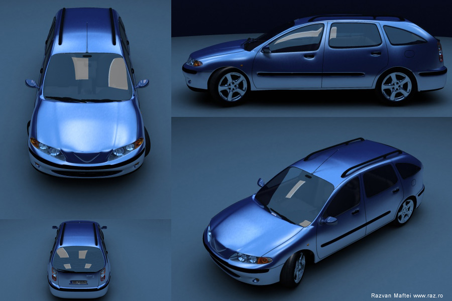
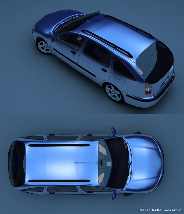
The first thing is to find some blueprints representing a car. I chose the blueprints of a Renault Laguna. The blueprints have to represent the car from the front, left or right, from top and eventually from behind. Useful are images from perspective (real pictures). I want to say, although I had used the Laguna blueprints, I didn’t intend to make a Laguna car, I only used them only for primary mesh. The rest is my imagination :) After you found the blueprints, make sure they are in different colors from the max colors (I modified my blueprints in Photoshop because they were black and white). After that you will create 3 boxes(with the same dimension as the blueprints)and place the blueprints on them. Is very important to align the 3 boxes in the scene that the top blueprint aligns properly with the front and the right just like in the image:
Now will trace the splines. We will make a network of splines after the contours of the car. Will trace from the right(or left) view the important lines of the car. After that, here comes the difficult part of aligning them after the other blueprints (top, face). We can correct ourselves, looking in Perspective. Don’t forget that will only build one half of a car, then we will mirror and attach the other part:
After that will have to create additional splines to create surfaces of 3 or 4 splines. We do that, because will use the Surface modifier that will create a patch where it finds 3 or 4 splines intersecting each other .
After finishing the spline network, we make sure that it doesn’t have any holes (if we apply Surface). Them will mirror the networks and weld the vertexes at the middle.
To better see what we models, we must make a reference of the spline network and apply to the reference the surface modifier (the original object remains without surface). This way, modifying the original spline network we will se real time in the viewport the smoothed surface reference modified as well.

Now will make the air hole. We create an ellipse and will modified it like in the image:
We cut the splines that are interceding with the ellipse and we create a copy of the ellipse and we move it to the interior like in the image
After we are sure that the spline network is fine, we applied the Surface modifier with the step 1 (or ventualy 0). We use step 1because next comes a edit mesh modifier(for the details) and it’s best to have minimum faces to work with.
Next is the rear bumper. We applied edit mesh like in the bottom image:
 After we select the rear faces we extrude them. Next will detach the rear end (bumper) for later editing.
![]()
We also extrude the window faces but in the following way: we select the windows, them extrude with a negative value (-1) then we extrude the result(it’s already selected) with a positive value (+1). We are careful if we select all the normals must be selected for the local not for the group.
We do the same thing for the head lights. We select the faces, them extrude them both ways (e.g.: -1.5,+1.5).
The fog lights : we select the vertexes under the head lights and chamfer them. After that, we select the faces that are resulting and extrude them deep down ( e.g.: -5).![]()
To check everything is all right we apply a mesh smooth with 3 iterations.
If everything is OK, we reduce the iterations from 3 to 1. At subobject (in mesh smooth) we chose vertex and select the vertices from the corners of the windows like this:
After selection we modify the weight of the vertexes from 1 to 2 or 3 because we don’t wont the corners of the windows to look to rounded. Next will take care of the protection bumper from the car doors. We select a row of edges and apply on them chamfer. We select the faces that resulted and applied chamfer (-1) first and them (+2) -to give the sensation of bump. Don’t forget to set the id of the faces to other material. The same goes for the faces of the windows and the headlights and the rear lights
The same goes for the front and rear bumper bar.
To give the light depth we select the headlights faces then we copy those faces, next we extrude them ( with a negative value). Then we detach the new faces that just formed:
The headlights mirrors are made from 2 spheres and a cylinder. The firs sphere is larger. We apply on it a edit mesh and select one of the top vertex (we have soft selection on), then we move the vertex inside the sphere until we have the shape of a concave mirror. Then we clone the objects (like in the image) and place them inside the headlights. We also create a dividing object between the signaling light and the rest of the lights.
Next we create the holes for the door handles : we chamfer an edge then extrude the resulting faces:
Next select the faces like in the image below and use the bevel modifier (from edit mesh):
Next we apply a meshsmooth with 2 iterations
Now comes the part of creating the contours of the windows, the door, etc… We will create these using splines. In the left view(or right) we create splines after the shapes of the windows and door.
We don’t have to align the splines in other viewports like we did in the first part of the tutorial because we’ll use a utility that will overlay the mesh.
For overlaying the splines on top of the mesh, will use the glue utility (you can download it free from http://www.itoosoft.com/english/freeplugins.html)
After that will have the splines glued to the mesh:
We need now to make those spline renderable:![]()
There are many methods for building a wheel, I’ll describe a simple one, but from there you could develop to a complex method.
First will create a cylinder and a tube with 20 sides. The cylinder must be inside the tube.
Next we select the vertexes 2 by 2 and we scale them (see the image). Then we weld the vertexes with the vertex of the cylinder (in the first place we attach the tube to the mesh). We must delete the interior faces that are resulting from the welding of the vertexes (it’s best to do this before the weld but it can be done also later). For a better effect we can select the central vertexes and spin them , or we could erase some faces from the middle to make the impression of holes.
We delete the faces from the exterior part of the mesh (that touches the tire). We apply a mesh smooth to see how it looks.
We return to edit mesh and select the exterior edges (marked with red in the image) and the interior one and we scale them:
We apply then a mesh smooth with 3 iterations:
The tire: We create a circle and a spline like in the image: We loft the spline on the circle and obtain the tire shape. If the tire is upside down we select the object, then subject (in loft) select spline , and we rotate the spline with 180 degrees.
This is how the wheel should look. Don’t forget about a the bump texture.
Another one (but more complex)

Please excuse my bad English :)
The side mirrors: We copy the faces from the corner of the window (before mesh smooth) and we detach them from the object. We apply edit mesh and align them as in this image:
Next comes a mesh smooth and a edit mesh. Select the central faces and extrude them like this:


Then select the faces that will represent the mirror and extrude give them another ID. Then mesh smooth the object.
The windshield wipers are build from boxes modified with edit mesh and bend (because the wind screen is curved). The boxes that you create must have plenty of faces for the Bend modifier to work fine.
Next comes the plastic thing( don’t know the translation sorry :) on top of the car. One thing is done from a box that is edit meshed.
![]()
After mesh smooth:
The interior of the car doesn’t have to be very detalied and very precise because it will only appear vaguely in the transparency of the windows. The first thing is to create the bottom part of the car (it doesn’t appear in the rendering but is important if we use a radiosity engine)
Next will build the chairs. I have started from 2 boxes that I edit mesh like this:

The little cushion that support the head is created from a torus with minimum settings , then edit mesh and we scale the vertexes that on the z axes, then mesh smooth.
The dash board is created from a network of spines:
Then we apply Surface:
The polygons we have to extrude are marked red in the image:
The polygons will be extruded several times:
We apply mesh smooth with 2 iterations:
The Driving wheel is created is build from a cylinder and a tube. Some faces of the tube is are extruded and them welded with the faces of the cylinder like that:


The gear changer : from a chamber box and a modified box:
On the chamber box we apply a noise then a mesh smooth. After that we edit mesh the object. Select the vertexes in the top-midlle position (soft selection is on), and we drag them down. We reduce the soft selection area, and pull up the vertex. Then we mesh smooth again.

The rear bench is created in a similar way as the front chairs:

Next comes a mesh smooth and a edit mesh. We select the faces from the down – center and we extrude them. Then we mesh smooth again.

The interior should look like this:


About The Author
You might be interested in