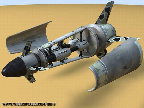
The Making of the “DMF – 239 Coyote” Missile
First of all here is a small introduction. I was briefed to build an aircraft-launchable missile, but this missile was special in that it had DMF capability (Dual Missile Fire). So this meant that I had to conceptualise a missile that could contain two smaller missiles inside itself, so that the mini-missiles could be fired off during flight.
So I have compiled together an informative tutorial of how I created this missile in 3D Studio MAX from concept to rendering. Unfortunatley this tutorial reads quite MAX specific, but I’m sure the techniques work over all platforms.
Enjoy.
CONCEPT
Well in the conceptual stages I got a lot of reference images of missiles from the internet, mainly using Google’s image search :). After looking at a whole bunch of different missiles and bombs, I came up with the initial design seen below.
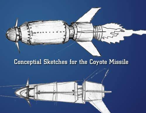
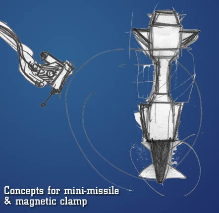
After I had sketched out the initial design of the missile, I had to create a way of fitting two identical missiles inside the larger, middle section of the missile. Not only did the mini-missiles have to fit, they also had to have a mechanism that holds them in place. Mechanical genius Dave Wilson helped me design the clamp mechanism. Basically it’s an remote electro-magnet that keeps the missiles in place. The polarity is reversed on release by remote signal, so that the mini-missiles are thrown from the main missile… cool huh :).
MODELING
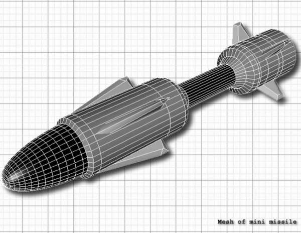
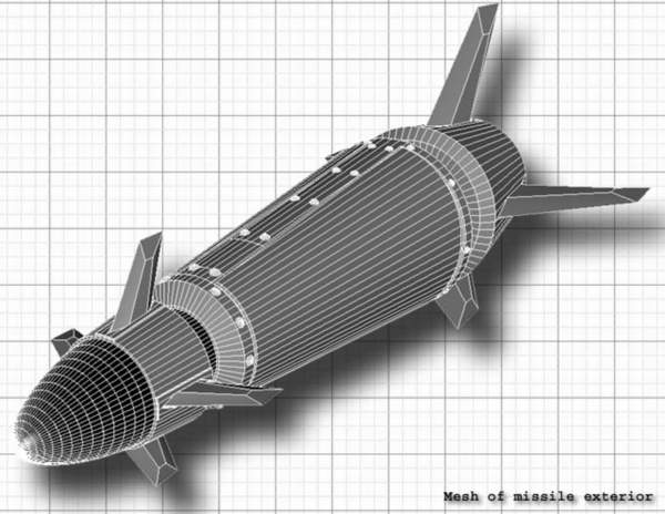
To model the missile I used polygons. To start off, I created a 64 sided capsule (MAX primitive polygon). I then edited the capsule by extruding, beveling and chamfering. I then hollowed out the mini-missile bay section of the missile using a boolean. Then using simple boxes, I cut out an intersection from the sides of the mini-missile bay, to create bay doors. I then went into more detail by beveling the edges of the bay doors and the bay area to create a seam for specular highlights to reflect off. For the fins I simply extruded and beveled out a spline and then tweaked the vertex positions to create the right kind of shape.
After the outside was complete I had to model the inside mechanics and the mini-missiles. Both the struts and clamps are extruded and beveled splines. The electro magnets are a bunch of boxes and cylinders with a few nips and tucks. Basically I used chamfer-edge to create bevel edges on every thing. The screws are manipulated capsules.
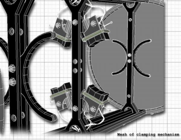
The mini missiles were also manipulated capsules, with fins added afterwards.
TEXTURING
After all that it’s finally time to dive into some texturing. Dave Wilson (author of Texturing 101) helped me considerably in this section. Firstly in the surface properties of the edititable mesh (3D Studio MAX) I’ll divide up the missile into multiple material IDs depending on the surface texture I want it to have and the angle the polygons are faceing, for different mapping types. For the main texture of the missile I used a cylindrical mapping. I use a plug-in called Unwrap Texture Object which exports the mesh to an image that can be imported into Photoshop. Once in photoshop I imported the mesh image for reference. Dave helped me with the initial texturing, he took an image of metal plating for a base texturing, then added all sorts of dirt, sunspots and decals. I then took over and added straches and weathering to the missile using the mesh as a reference to where they would be.
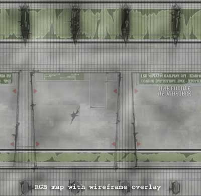
The most important part of the texturing procedure is to keep the texture map in layers. This means after you’ve finalised the RBG texture map, you can desaturate, then change the brightness and contrast of the layers to create your bump and specular maps.
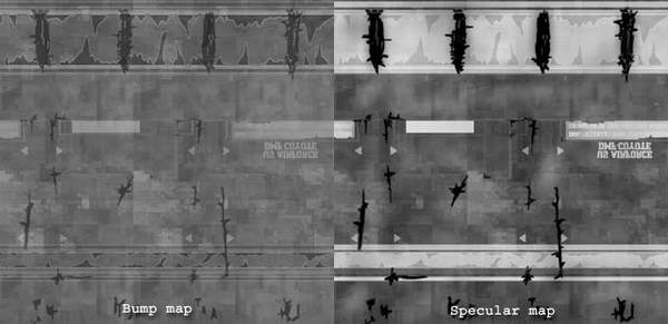
I’m not going to explain all the texturing because that will that quite some typing :). Basically the rest of the objects varied between texture maps and procedural textures.
RENDERING
To show off the model in all it’s glory I wanted to render an image of it in “Radiosity Land”. Unfortunatley 3D Studio MAX doesn’t come with out-the-box global illumination rendering software. So what I had to do was improvise, instead of lighting an entire scene with one light I’ll do it with 33 :). Below is an image of my scene
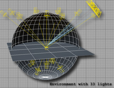
To start off the explanation, I have two scene objects. The round globe is an inverted sphere with a very white blue self illuminant texture. The ground plane is a simple plane with a matter orange brown texture. Now on to the lights. Above I have 9 angled white blue lights only giving off diffuse light (no speculars). Each one has a very low intensity, so they don’t flood the scene with light. The same goes for the bottom 5 lights, except they are of a light orange colour. The white blue lights give the GI (global illumination) effect of the self-illumanant sphere and the orange lights give the GI effect of the ground bounce. The main light source comes from an array of 20 lights. What this accomplishes is the soft shadows you get with real lights i.e. the further an object is away from it’s shadow, the more blurry the shadow. Below is a close up on the array.
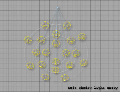
The lights have a path contain to a circle. This way as I’m tweaking the shadow’s appearance I can easily change the radius of the shadow blur by changing the radius of the circles. Since there are 20 lights the intensity has to be incredible low so that they don’t flood light. Also to increase the illusion of global illumination, I took the specular maps for all my objects, and used them for the intensity level of raytraced reflections.
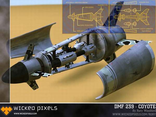
Well after all that, have a look at how it all came out below.
Cool huh :). Below is a wallpaper I made from the above image with added photoshop effects. You can download the fullsize image (1152×864) right here.
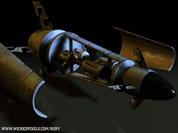
And here is a moody lighting render of the Coyote missile. I used two lights, a shadow casting main blue white light at 1.25 intensity and a orange backlight at 0.6 intensity.
If you have any further questions or queries please contact me rory@wickedpixels.com

