How to create a car using the polygonal modelling
English version by: Claudio Magri & AnnaRita Taddeo Benoit (Professional Translator).
I have written this tutorial to help people who doesn’t know the bases of the polygonal modelling. To realize this, I have used an example that has been useful to show you some interesting techniques in this field. The example that I have chosen is to model a simple car starting by a standard primitive: a box.
The software that I have used to realize it is: 3DS MAX 4.2 . You will see that many of the principles that I will explain you are right even if you will use other 3D software . You will be able ,therefore ,to use the techniques that I will show you in order to model other objects or to arrange this techniques that you already know .In this tutorial I don’t explain the meaning of the words such as Extrude or Outline, you will see that they will be used in an intuitive way.
Let’s start.
First Step. CREATE A BOX AND SUBDIVIDE IT.
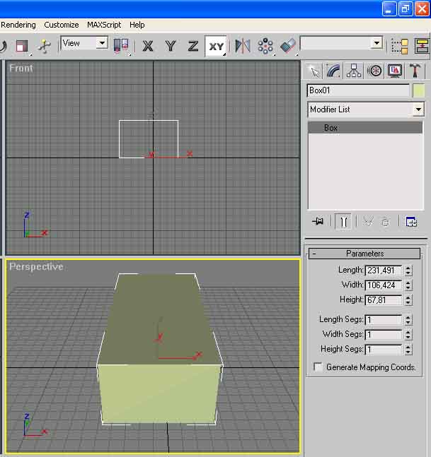
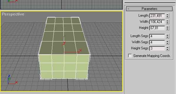
Select from the panel at your right:’ Geometry’ , ‘Standard Primitive’ , ‘BOX’, and generate it. As you can see it isn’t subdivided in many polygons. Pay attention to generate it with similar parameters that you can see in the graphics eg: Length 230, Width 106 Height 67.It’s important that the shape of the box is lengththened. After that we need to subdivide the object in polygons, it’s really easy set the values of the Length, Width, Height like the graphic here above. To look at the result of the subdivision on the box press F4.
Second Step. START THE MODELLATION. (Begin to model the parts of the car)

With the right mouse button click on the box when you see the dialog windows select: ‘Convert To’:’ Convert to Editable Poly’. Then select Polygon from Selection. Now we are ready to select the polygon of the object that we want to modify. Press Ctrl and continue to press it , with the left button of the mouse click on the four polygons that you can see here above.
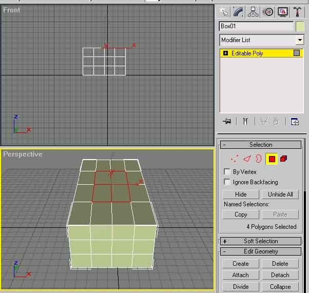
Flowing the panel Select you can find :’Edit Geometry’, set the values of extrusion at, for instance – 3 to begin (use negative values for this example) and dosed the use of the outline value. Sometimes in this case we use negative values (-).We have created the driver’s cab .Have a look above to the graphic.
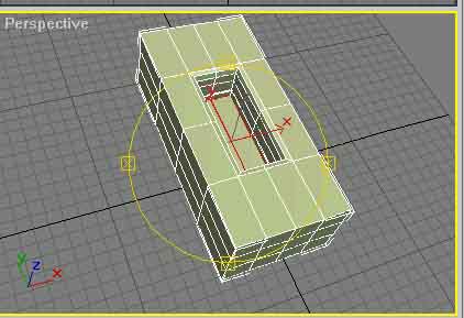
Let’s go on. About the wheels .To create them, select two polygons parallel to each other on the both sides of the box ( Fig.1) ,slide down the command panel and click on Subdivide, under Tessellate select ‘Face’ click on tessellate, select now ‘ Edge’ and click again on Tessellate. The final result is visible on the (Fig.2) .Select now the middle of the polygon obtained by both sides of the box (Fig.3).Return on the ‘Edit Geometry’ and by dosing the values of extrusion and outline to obtain a final result the most similar as possible as (Fig.4).
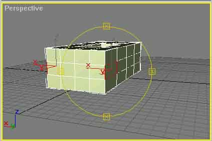
Fig.1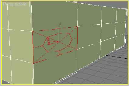
Fig.2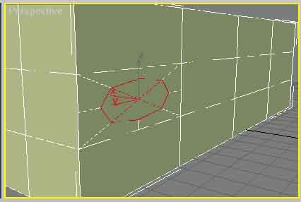
Fig.3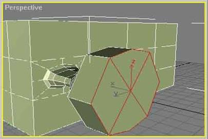
Fig.4
Now a very important thing. To create the re-enter of the wheels I have used a technique that I’ve called ” Extrusion In Site”;, how to realize it ?We stopped at the (Fig.4)now set the values of extrusion at 0,001 and press Enter we obtain an in site extrusion. It’s seems nothing has happened , it’s only an impression because this will help to realize the re- entrance of the wheel using ‘outline ‘(Fig.5).This technique can be used to create the silencer, and the beginning technique of the creation of new polygons to realize the wheel (Fig.3), and it can be used to create the lights of the car. Now enjoy yourself by creating what ever you want.
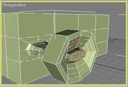
Fig.5
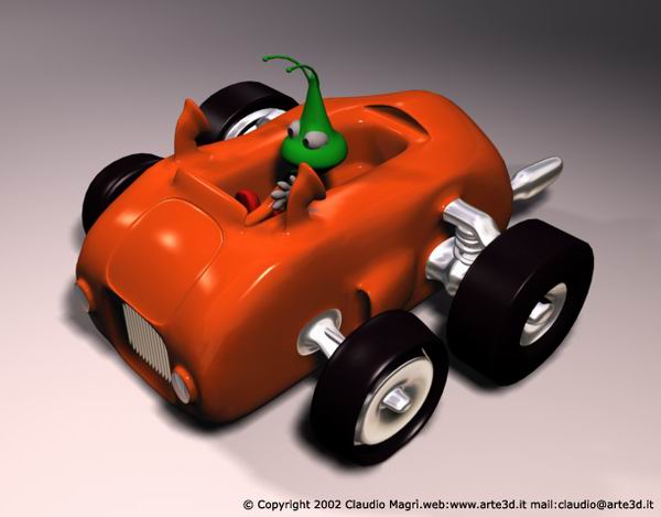
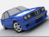
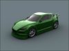
To go on quicker on the creation of our car, I let you see the final result of my work. I know that at the beginning you may find some difficulties , doing exercises you’ll see that you’ll enjoy yourself by using the polygonal modelling .The final results and the pictures of the car without the classical low poly angles have been obtained by setting a Mesh Smooth value equivalent to 2.I hope I have been helpful.


About The Author
You might be interested in