Modeling Sony Ericsson K530
Modeling Sony Ericsson K530. In this tutorial I want to show you how to model Sony Ericsson K530i in 3ds max.
Introduction
In this tutorial I want to show you how to model Sony Ericsson K530i in 3ds max.
References
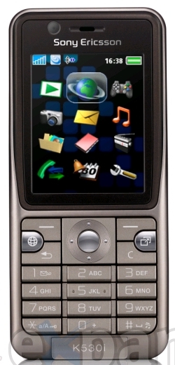
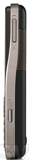
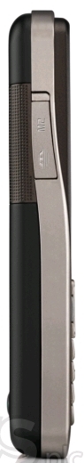
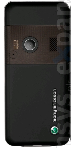
![]()
Setting up the scene
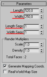
Step 1
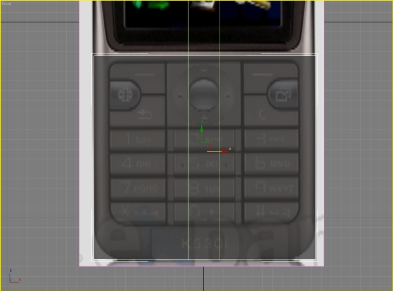
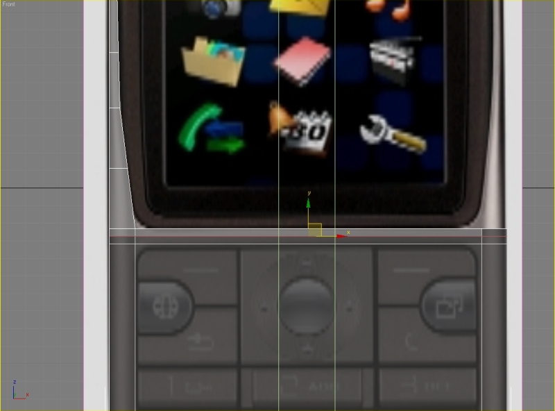
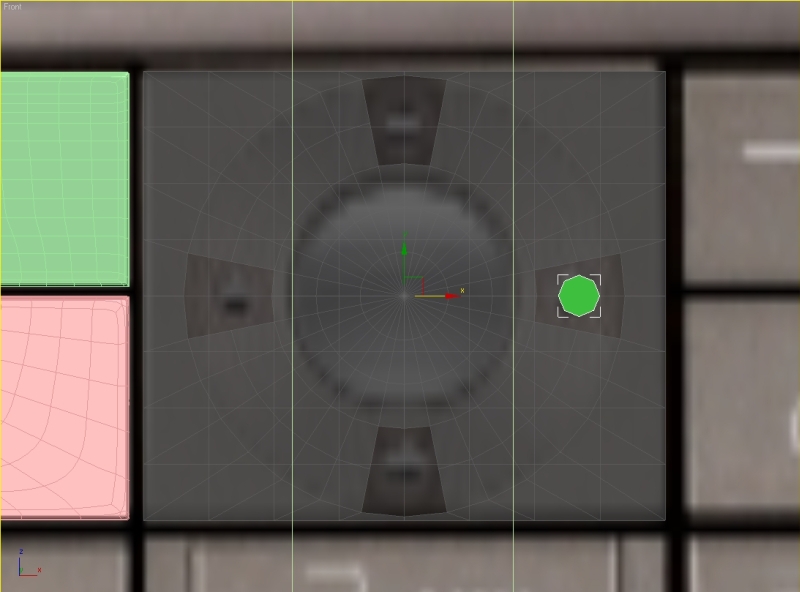
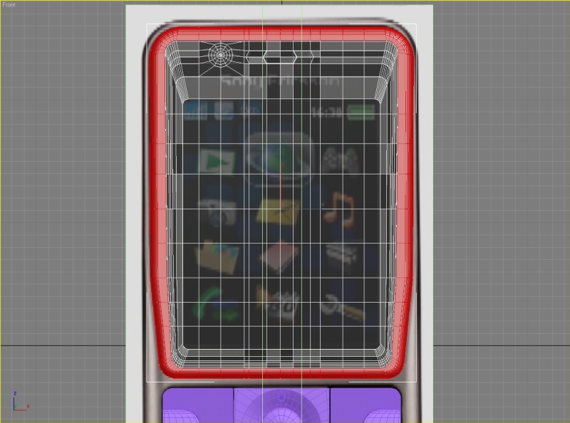
First we need to create some planes for our reference images. Go to the front viewport and create a plane with width 250 and length 520. Also lower the plane segments to 1.
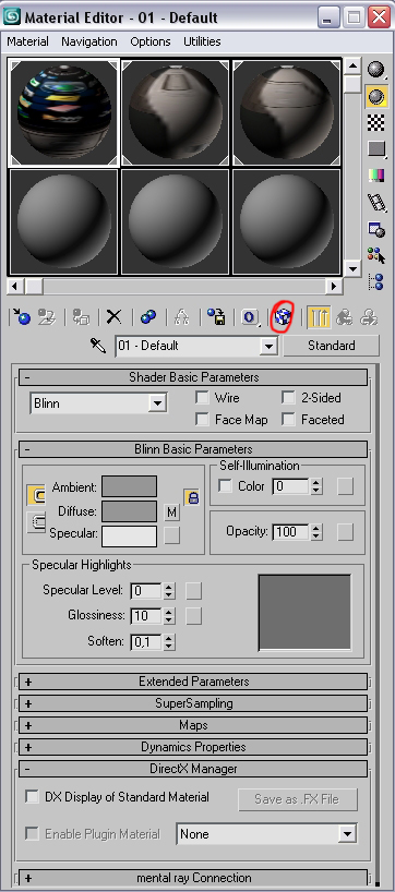
Go to the material editor by pressing M, hit the small button near the diffuse map color, in the Material/Map browser go to bitmap and find the reference image(the front view).
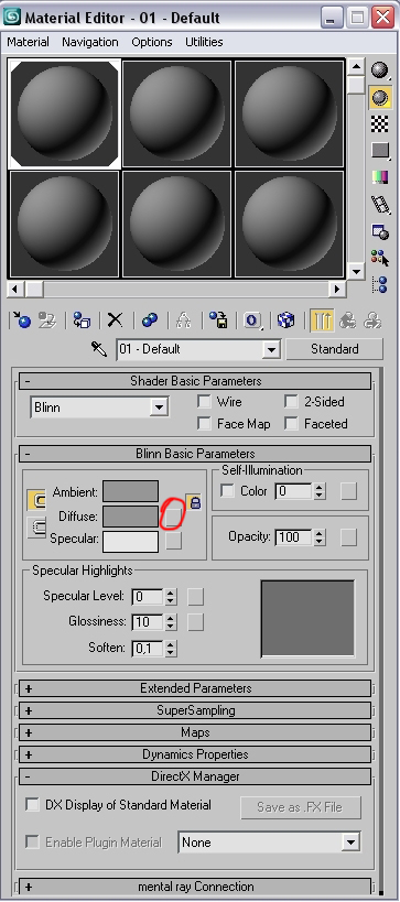
Also don’t forget to press the Show map in viewport button.
Step 2
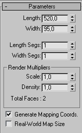
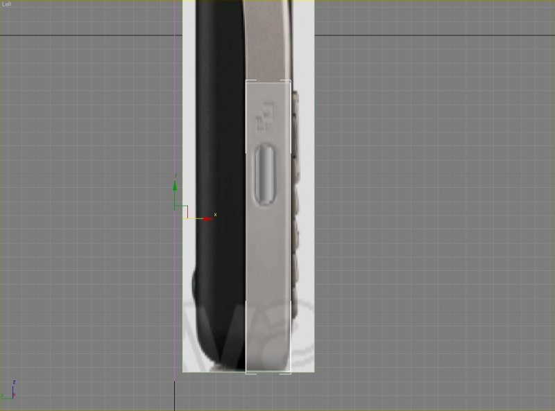
Now go to the left viewport and create another plane with width 95 an length 520.Set segments to 1.
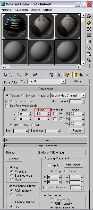
In the material editor repeat the first step but now search for the left view. From our images it’s the second one. Set tiling to -1,0.
Step 3
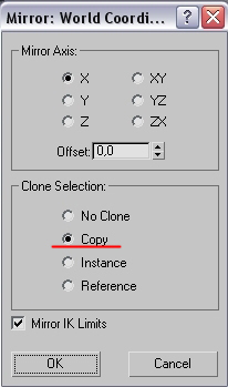
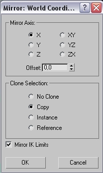
Now we need to make a copy of the plane we’ve just created. Select the plane and hit Mirror.

In the clone selection choose Copy and hit ok.
Go to the material editor and repeat the first step, but search for the right view.
Modeling
Step 1
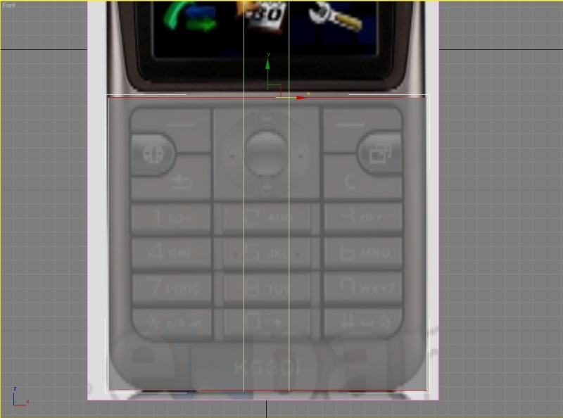
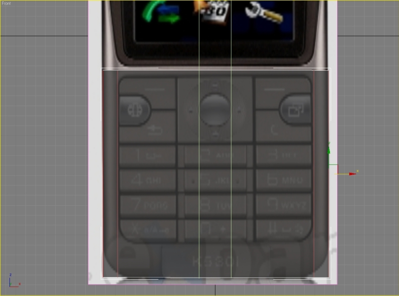
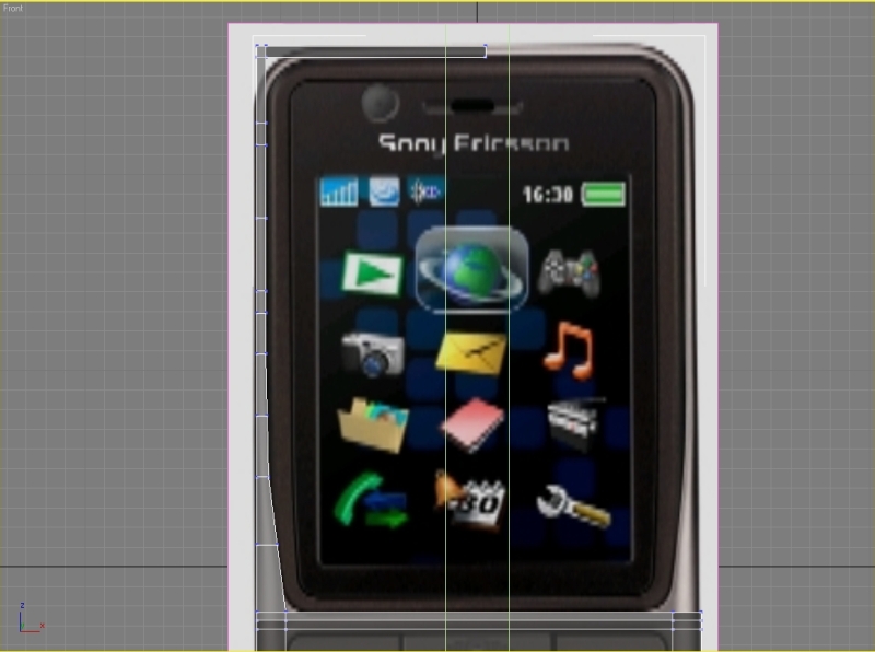
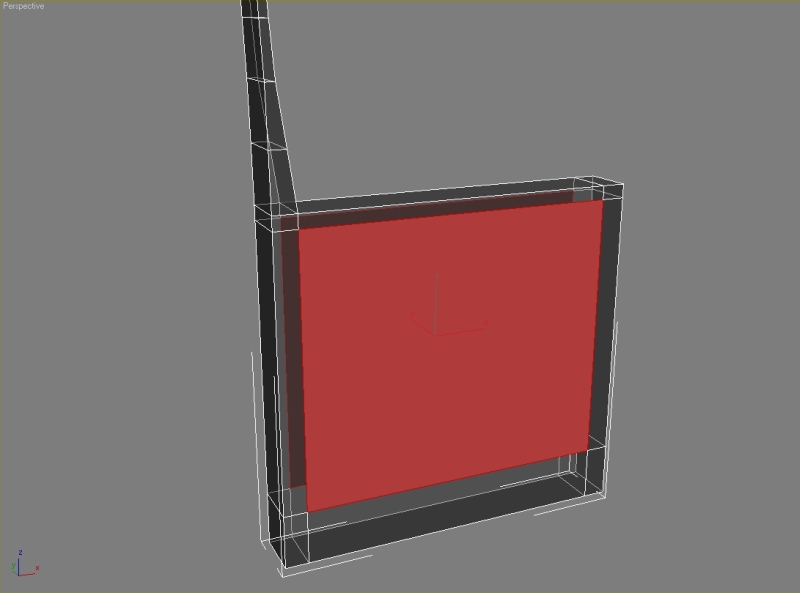
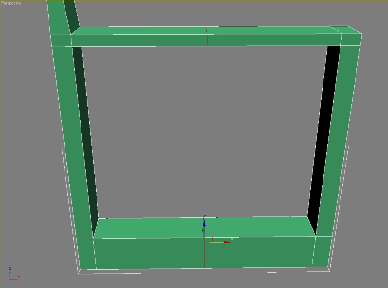
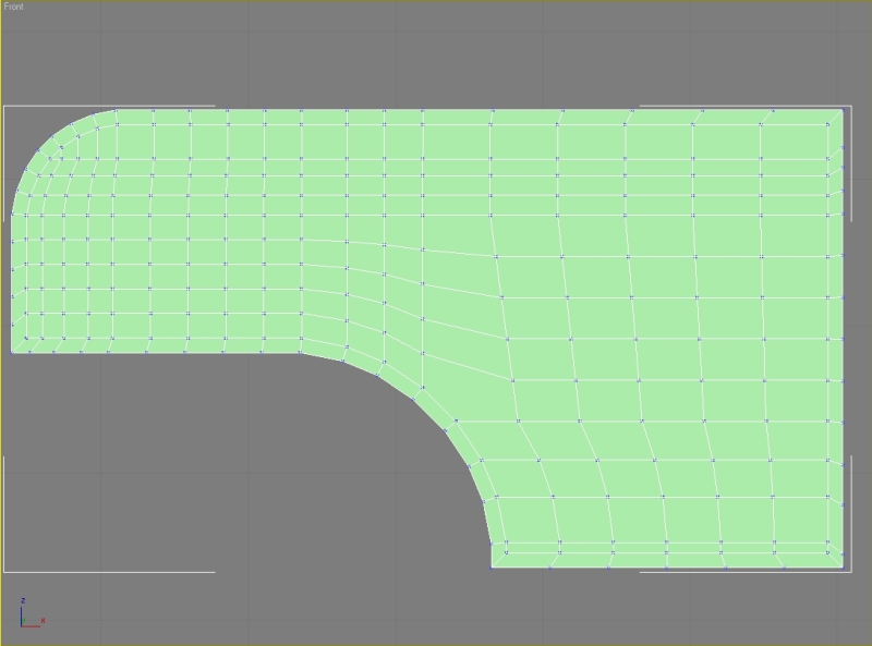
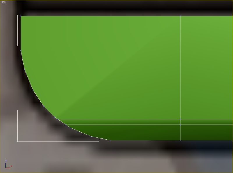
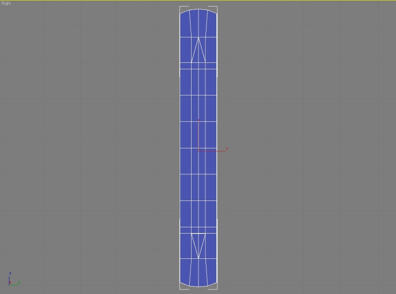
In the front view create a box. Convert it to editable poly. Fit the box to the reference image.
Also don’t forget to fit it from the left viewport.
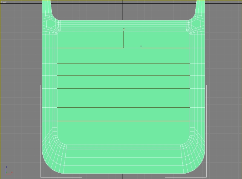
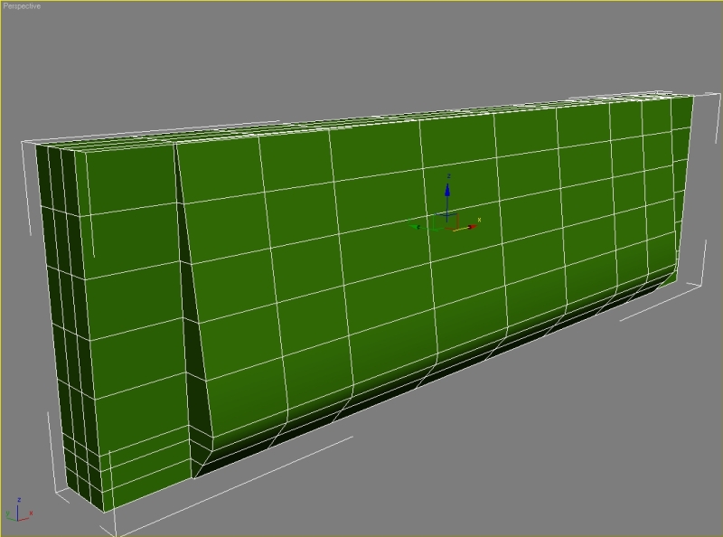
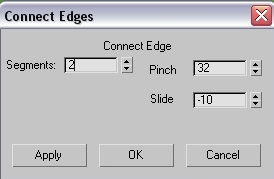
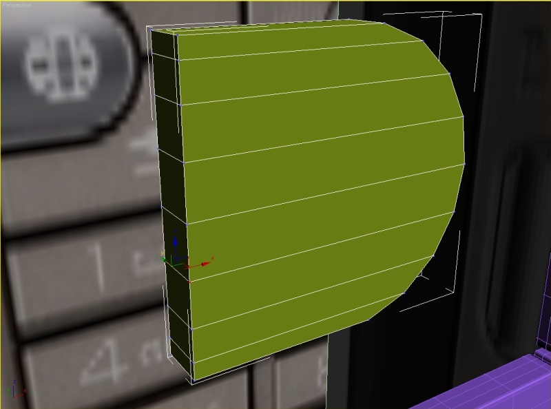
Select the top and bottom edges and connect them.
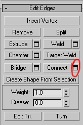
Set segments to 2 and Pinch to 84.
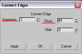
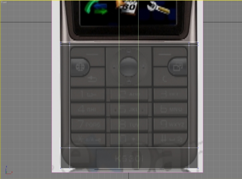
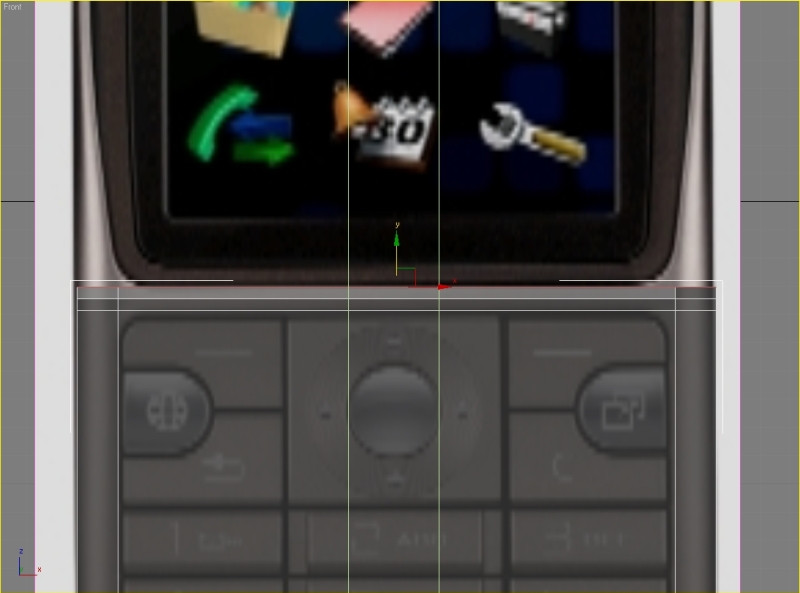
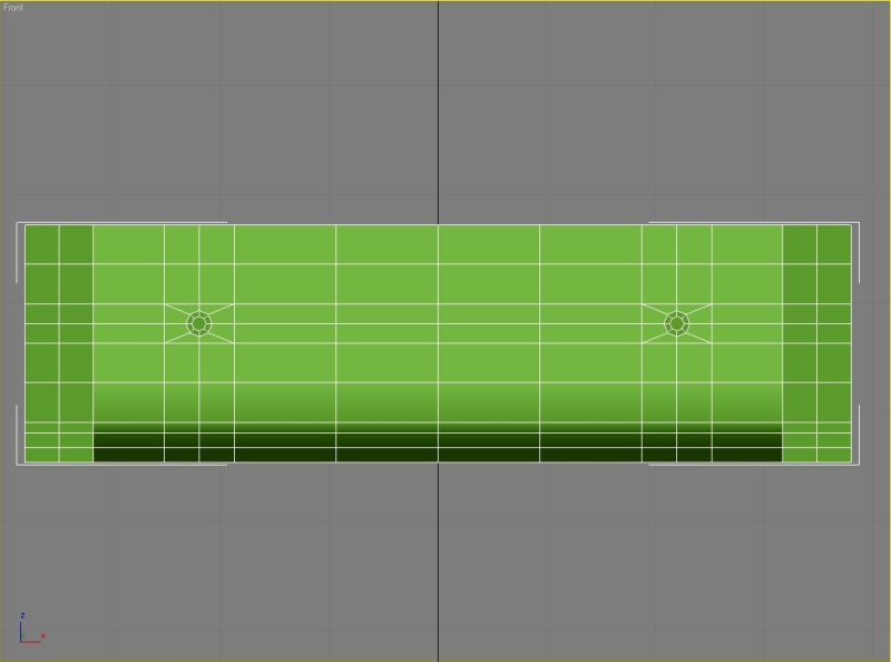
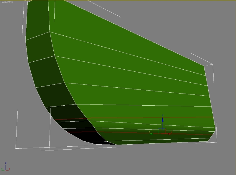
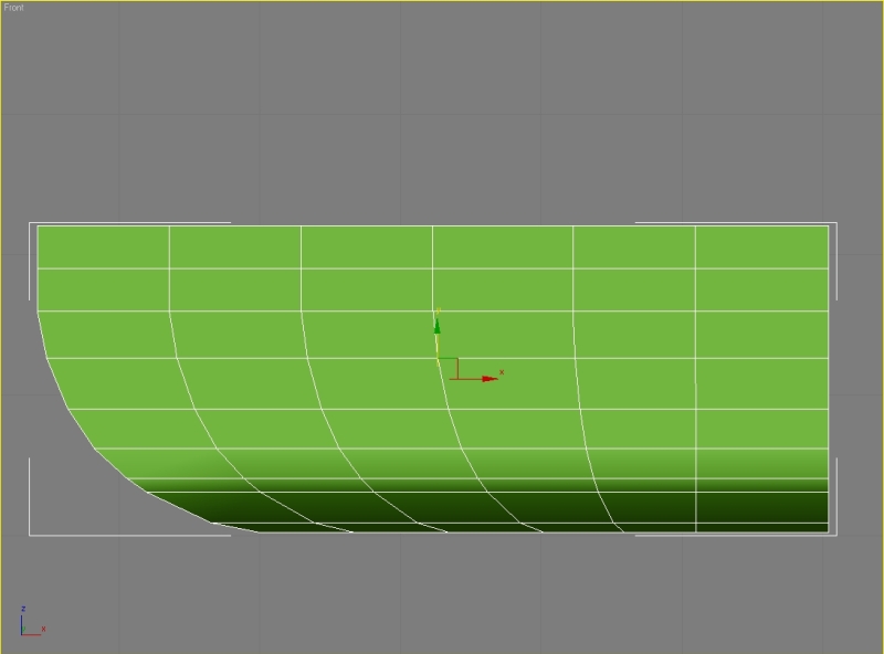
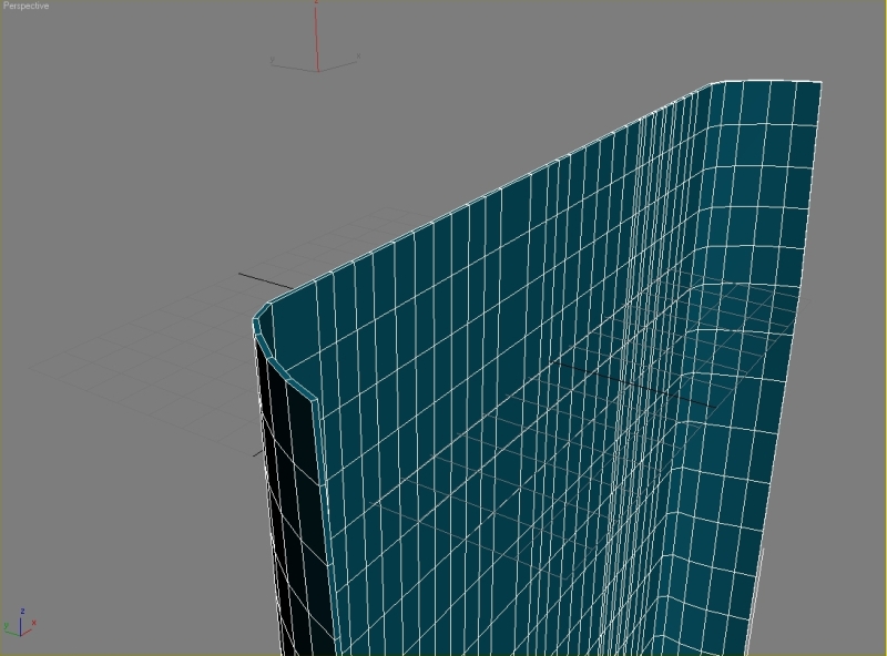
Now select all the vertical edges and connect them.
Set segments to 2 and Pinch to 0. Move these edges to the position like shown on the picture.
Step 2
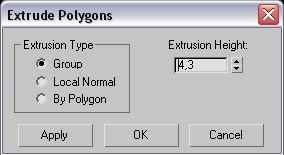
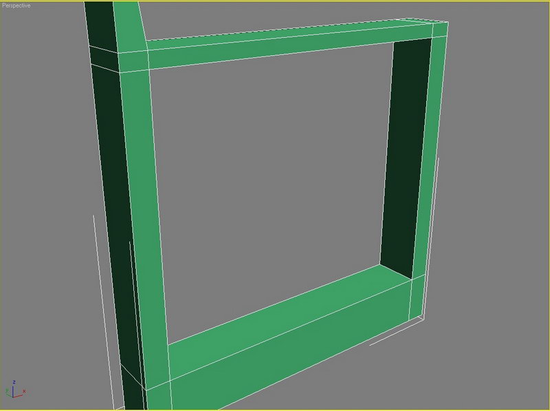
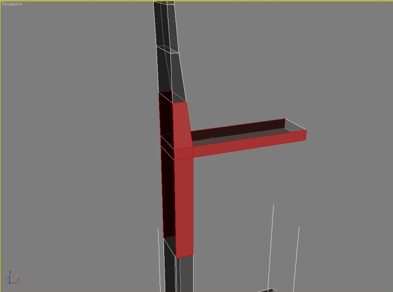
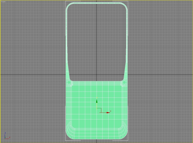
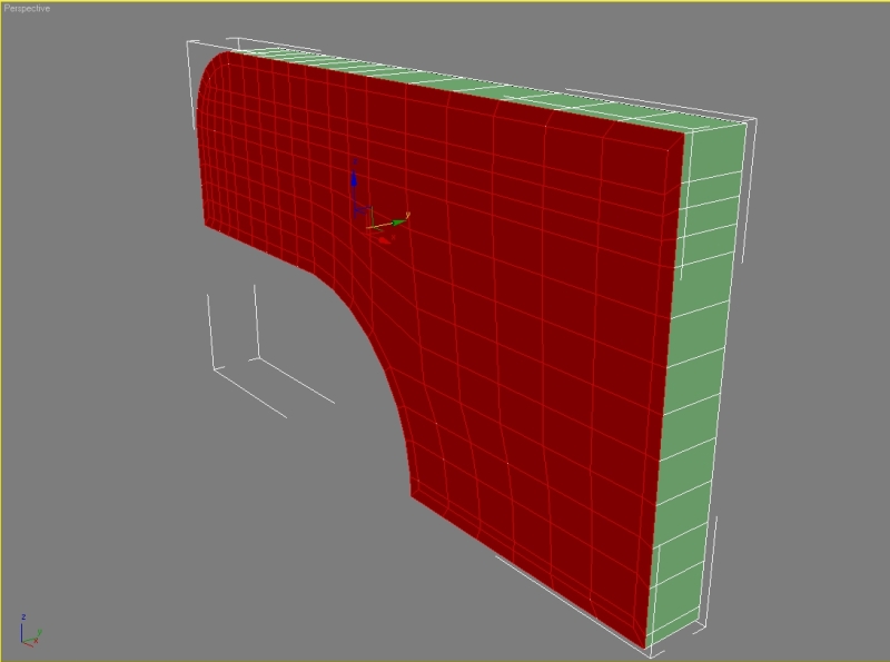
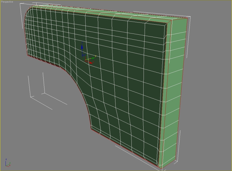
Select the top side polygons and extrude them.
Set extrusion height to 4,3.
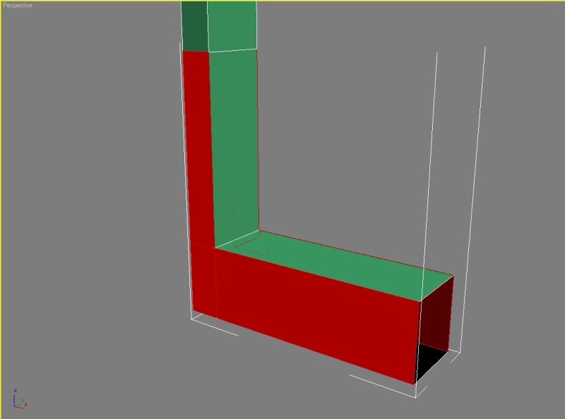
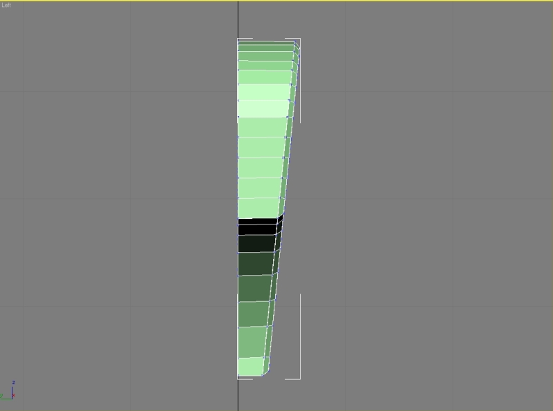
Select the left top polygon and extrude it to get a result like this,
again don’t forget to move the polygons from the left viewport.
Step 3
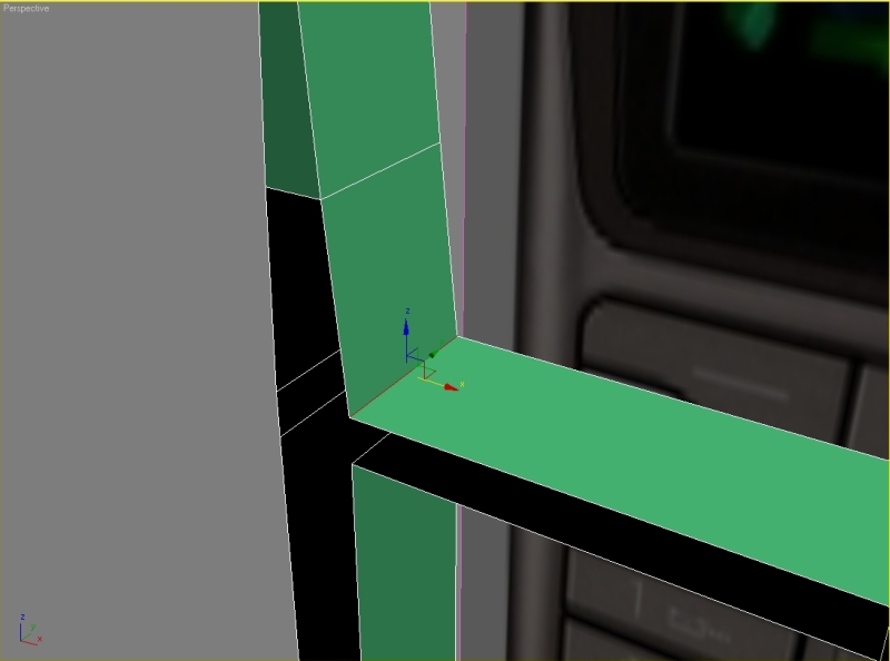
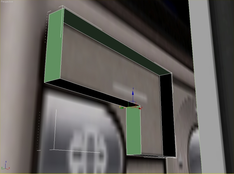
Delete these polygons.
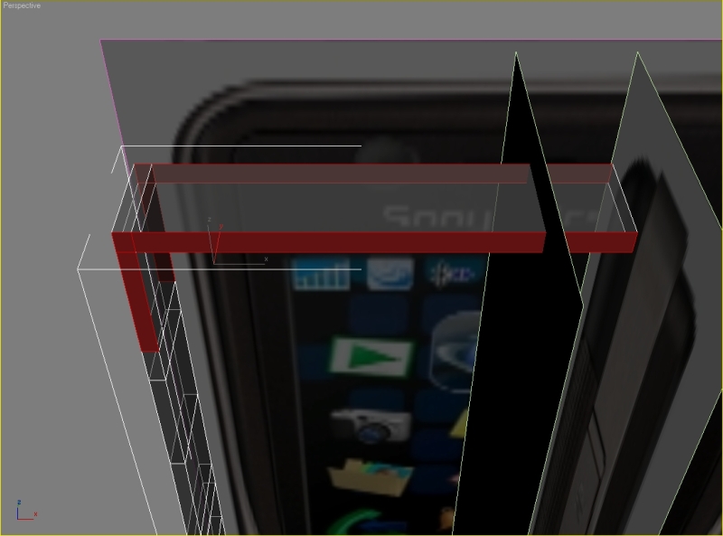
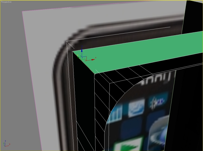
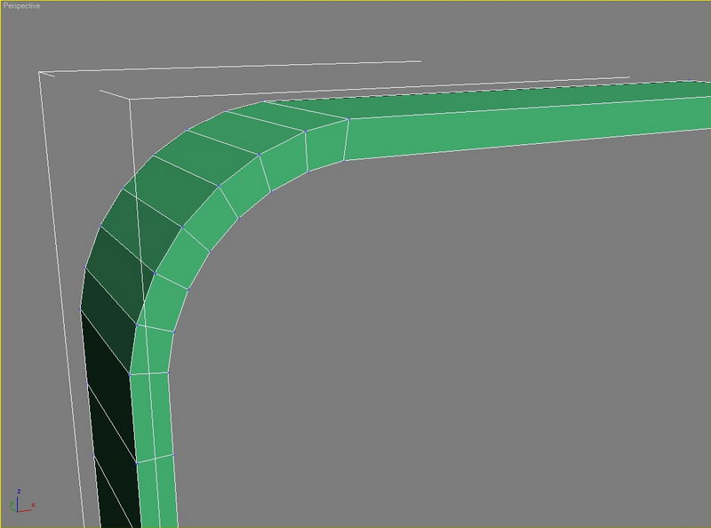
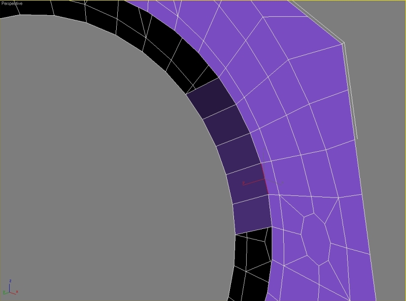
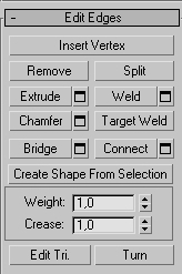
Select the inner edge and chamfer it.
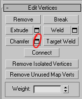
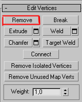
Set chamfer amount to 15, hit apply, then set chamfer amount to 5,5, hit apply again, set chamfer amount to 2,5 and hit ok. You now need to remove these edges so select them and press the Remove button (don’t hit delete!!). Also you need to remove the vertexes.
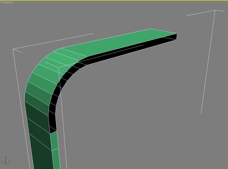
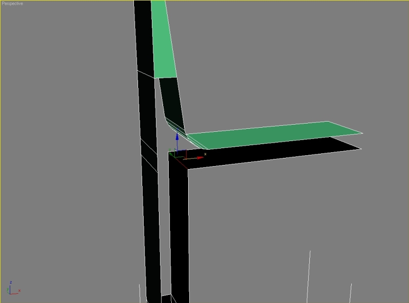
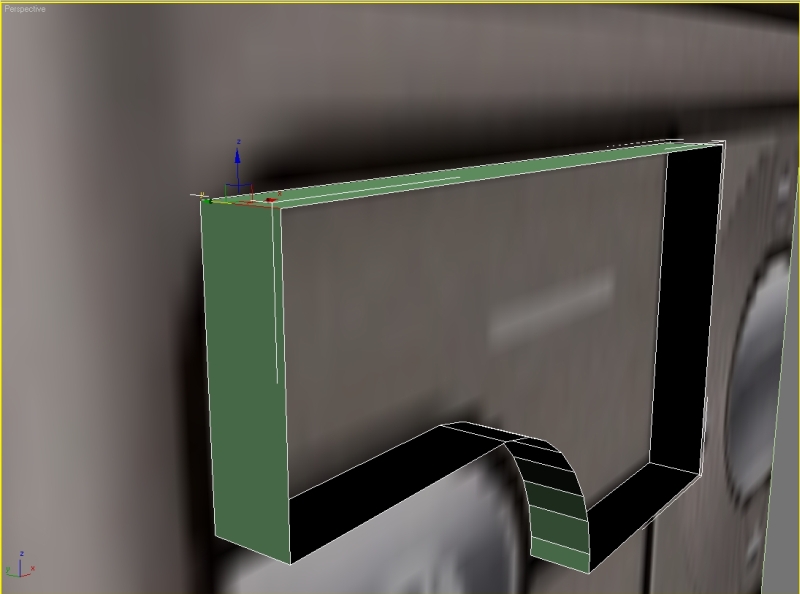
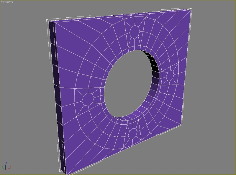
Select the edge and chamfer it.
Set chamfer amount to 18,5, apply – chamfer amount 6,6, apply – chamfer amount 3, hit ok. Now we need to cover the holes.
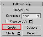
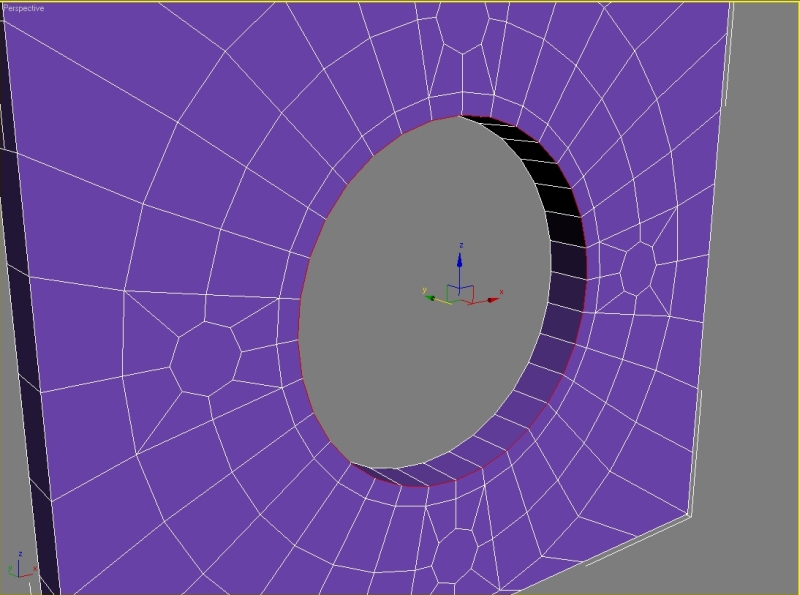
Go to polygon – edit geometry – create.
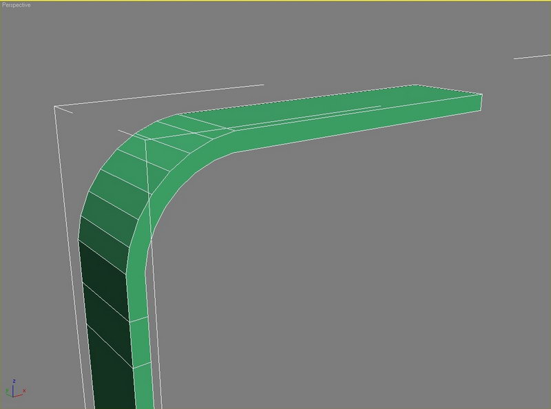
You should have result like this (don’t forget to cover both sides).
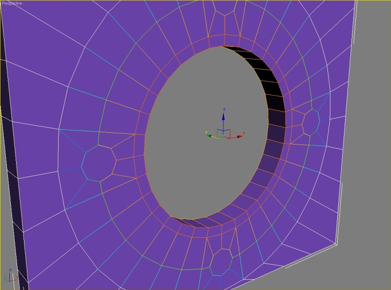
Now connect the vertexes.
Step 4
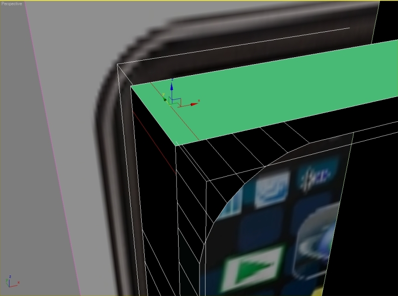
Remove this edge and vertexes.
Also delete these two polygons.
Go to polygon – edit geometry – create and cover the holes like on the picture.
Create an edge in the middle.
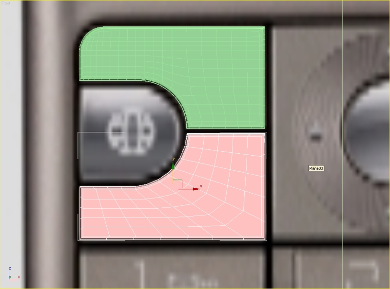
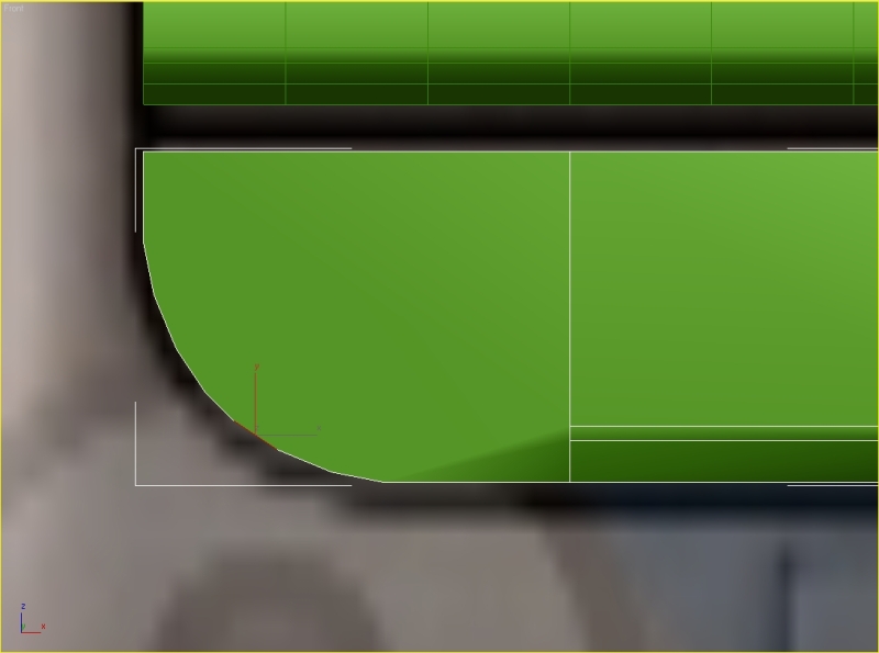
Delete the right half and also these polygons and start chamfering the edges.
Step 5
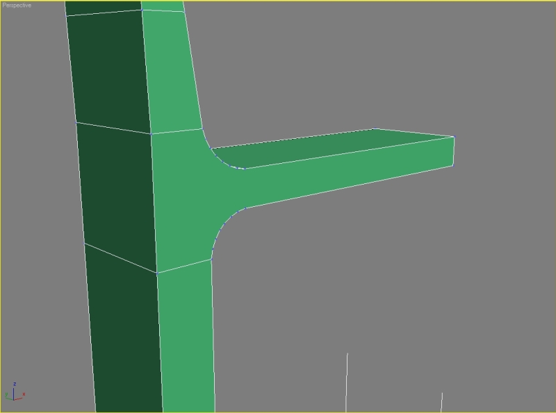
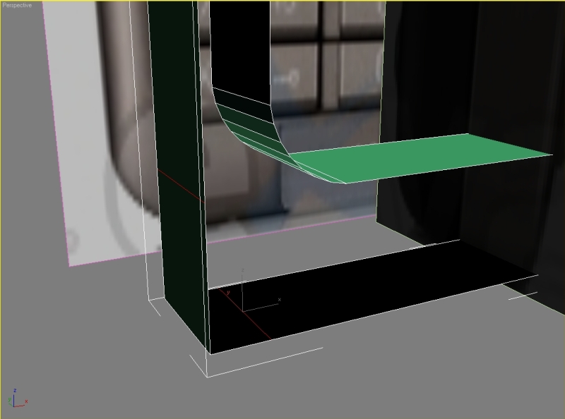
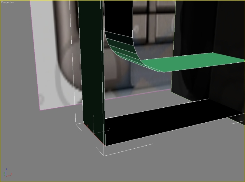
Select the first edge, press chamfer, set chamfer amount to 6,5, apply – set chamfer amount to 2,5, apply – then set it to 1,2 and hit ok.
Select the second edge and repeat the step with same parameters.
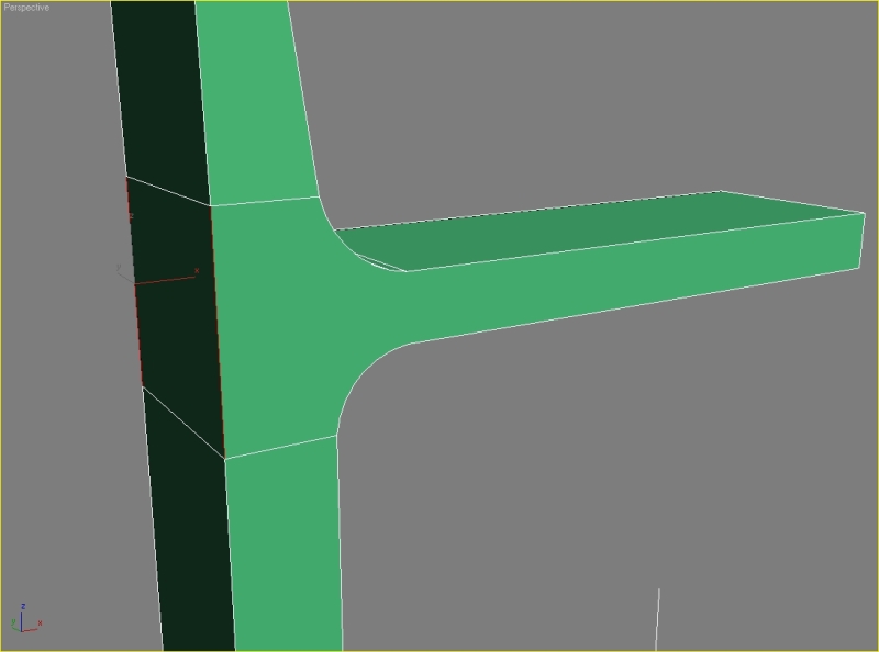
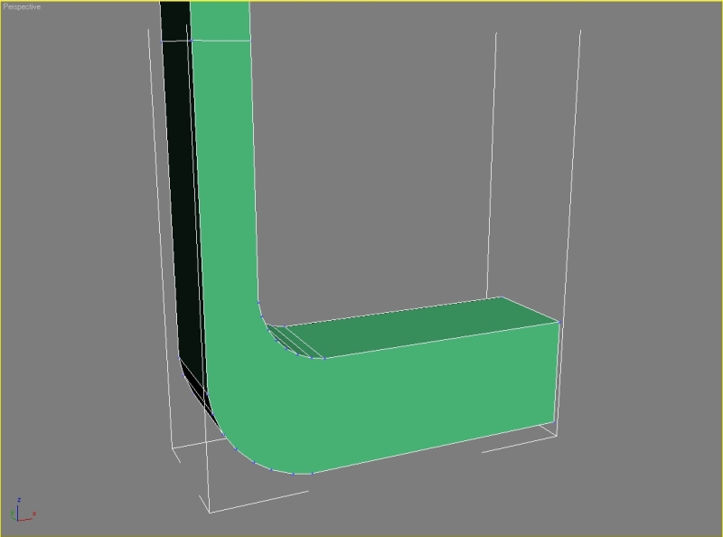
Start creating the missing polygons.
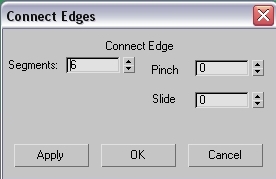
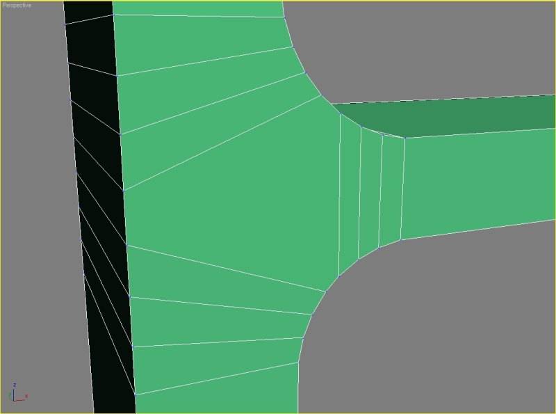
Connect the edges, set segments to 6.
Now just connect the vertexes, your result should look like this.
Step 6
Delete these polygons.
Select the third edge, hit chamfer and type these parameters: chamfer amount 12, apply – amount 4,5, apply – amount 2, ok. Remove the edges and also the vertexes.
Select the edge and chamfer it with parameters: chamfer amount 19, apply – amount 7, apply – amount 3, ok.
Create the missing polygons like on the picture.
Connect the vertexes.
Now just add some more segments to our model.
Step 7
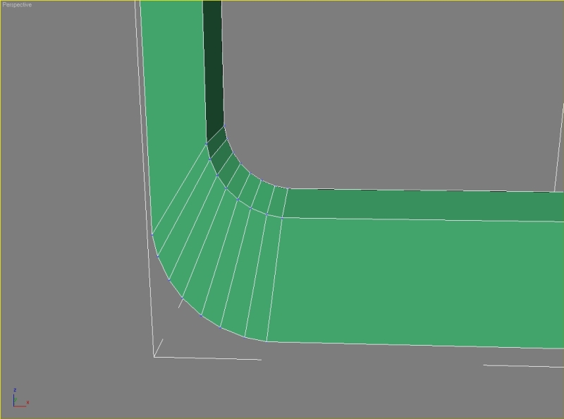
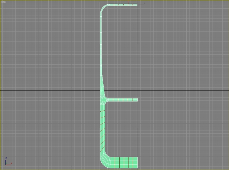
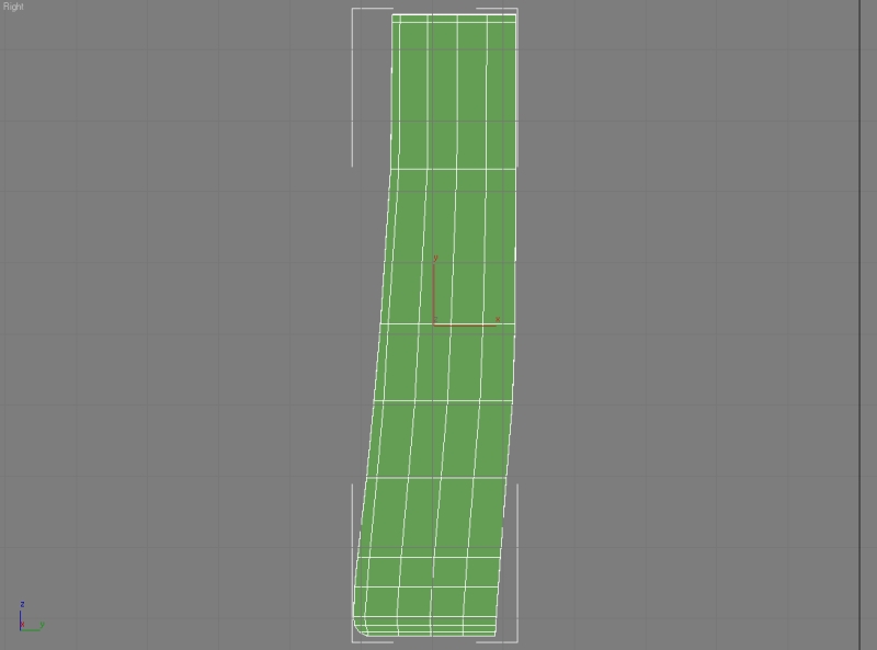
You can remove these segments and vertexes. Move the vertexes so we can have nice straight segments.
It’s time to mirror our selection. Attach them and weld all the middle vertexes together. Move the right half to fit the image.
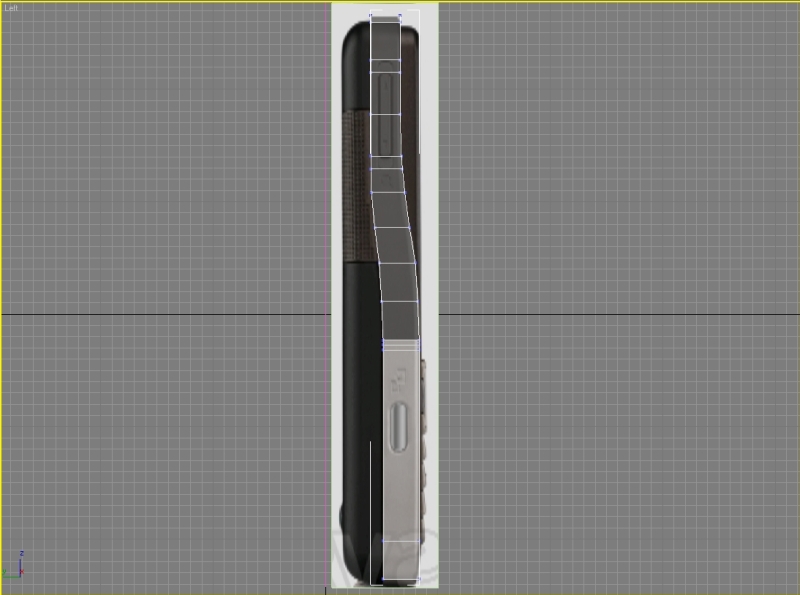
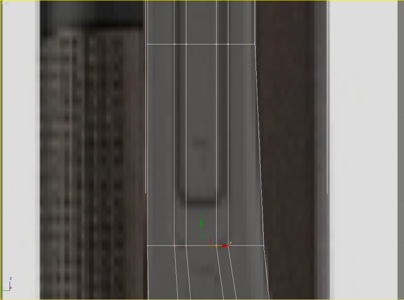
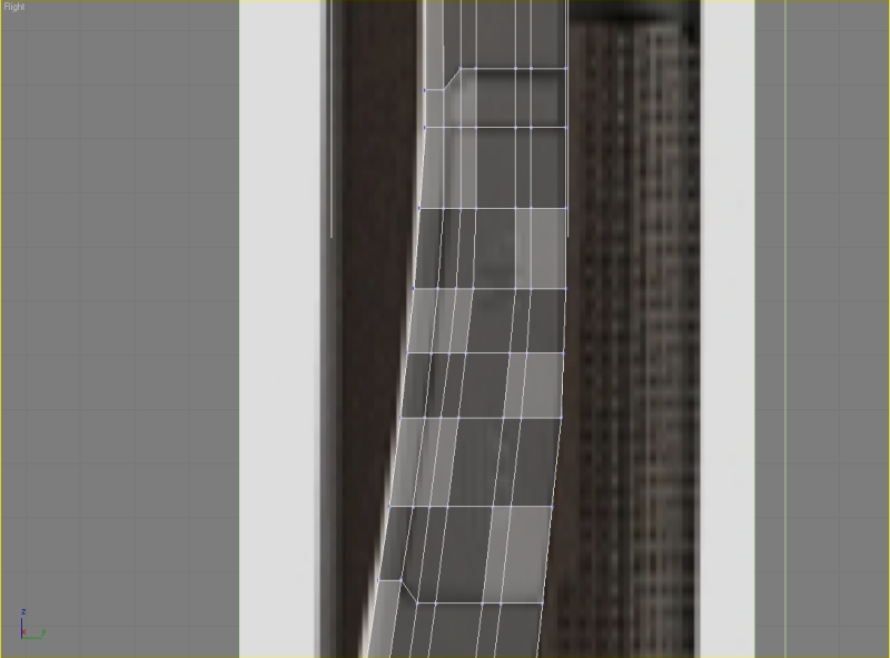
We now need the right viewport. Move the vertexes so we can model the cover for the memory card. We need to add one more segment, select one of the edges and hit ring and connect them.
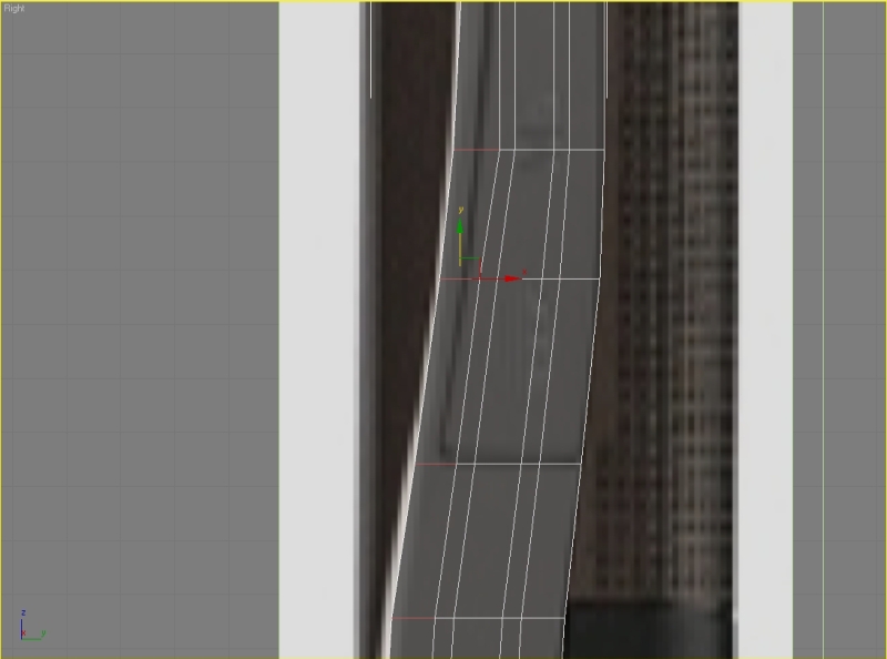
Move the vertexes. Pay attention because we want to move only the right side. Add some more segments and move the vertexes. Scale the vertexes.
Step 8
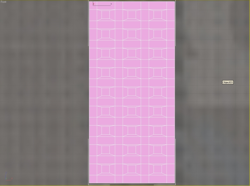
Now we are going to model the keyboard. Remove the edges and vertexes. Select the polygons, press shift and drag them to create a copy. In the clone part of mesh select clone to object. Flip the nomals, go to the modifier list and find cap holes.
Convert it to editable poly. Select the front and back polygon, press inset, set inset amount to 3 and hit apply. We can delete these polygons. Move the planes to the position, attach them and start welding the vertexes together.
Now connect the horizontal vertexes.
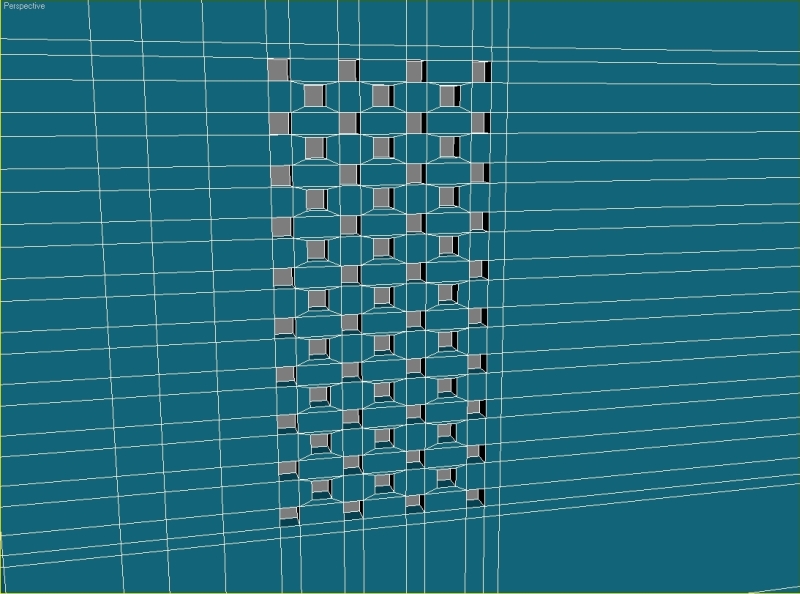
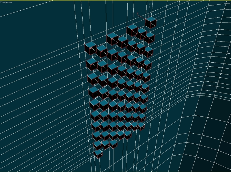
Now select the edges, hit connect, set segments to 7.
Step 9
Create a box and delete the polygons. Select the edge and start chamfering it with parameters: chamfer amount 8,5, apply – 3, apply – 1,5, ok.
Select the second edge, click chamfer: chamfer amount 4,5, apply – 1,75, apply – 0,8, ok.
Cover the holes. Inset the polygons, set amount to 1. Start connecting the vertexes and making new segments like this.
Select the polygons, hit bevel and set height to 0,5 and outline amount to -0,5. Select all the edges, hit chamfer, set amount to 0,01.
Rotate the edges.
Model the next buttons (everything is simple box modeling, chamfering the edges, inset, connecting, etc.).
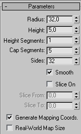
For the navigation button we need to model a box first, then some cylinders and we need to attach them together. So model a box first.
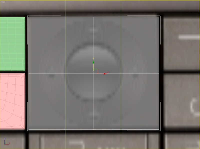
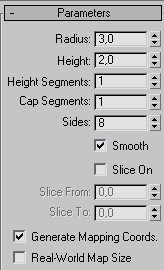
Now model a cylinder with these parameters.
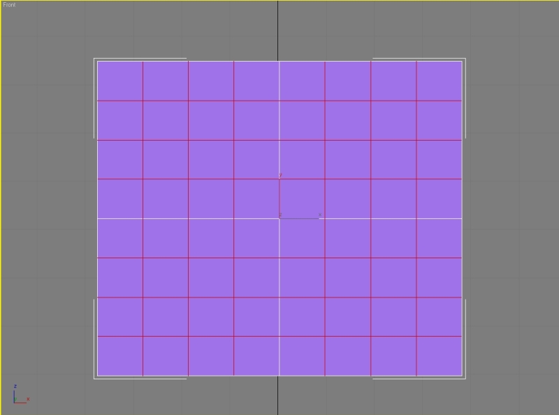
Select the box and add 3 horizontal and 3 vertical segments.
Convert our cylinder to editable poly and delete back and side polygons. Now select the box and delete the front polygons. Attach the objects. Select the opposite edges and hit bridge.
Continue making bridges. Delete the polygons.
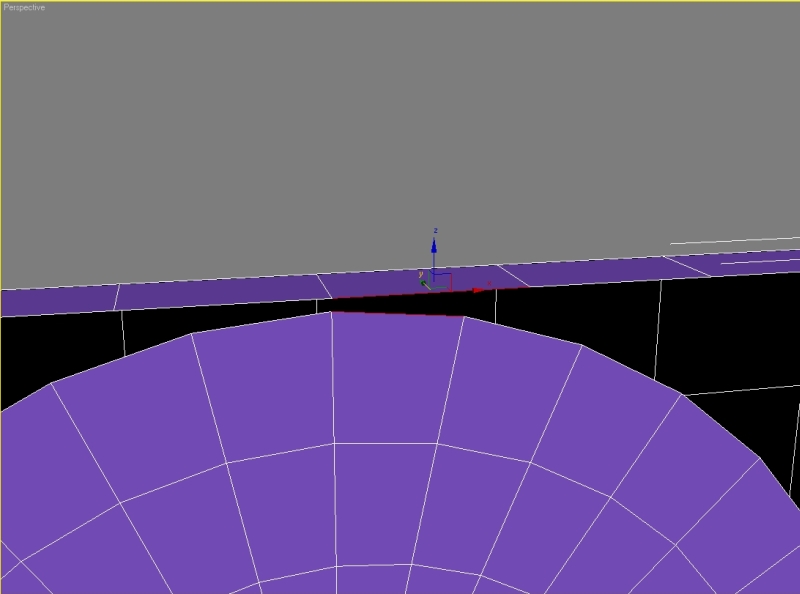
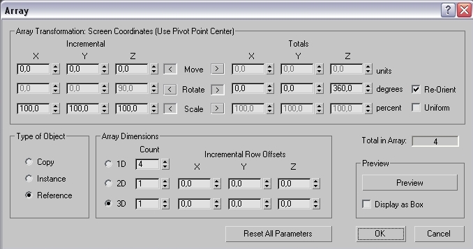
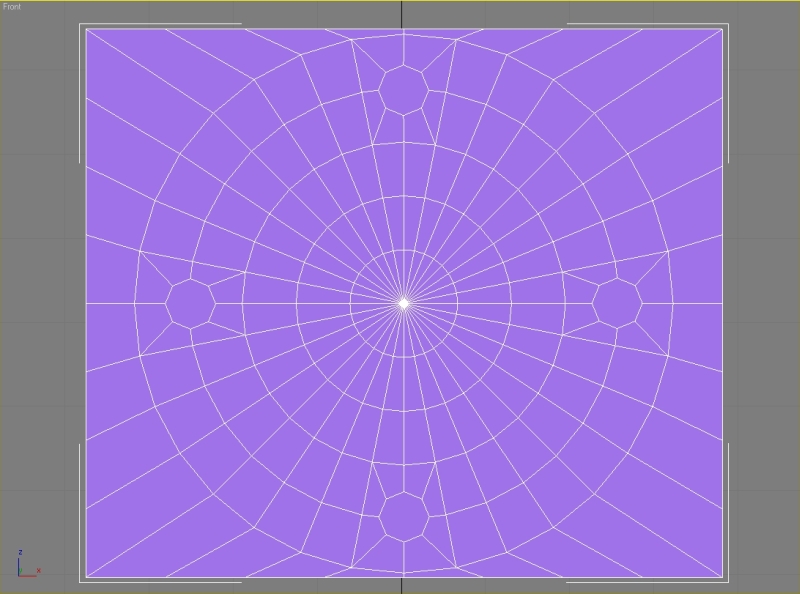
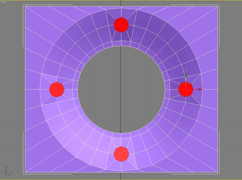
Go to the front viewport and create another cylinder, go to hierarchy – affect pivot only, move the pivot to the center of the box. Go to Tools – array and set these parameters.
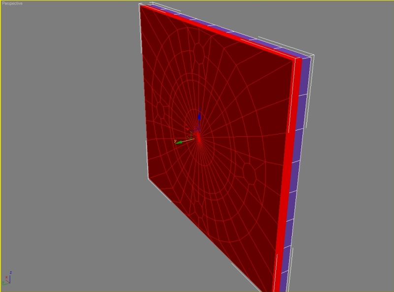
Convert the cylinders to editable poly and attach them. Delete back and side polygons and attach them to the box and start making bridges.
From the top viewport create one segment, delete the back polygons, mirror the selection and weld the vertexes.
Delete the polygons and again bridge the edges.
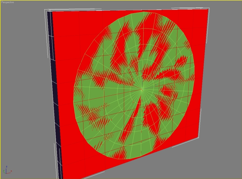
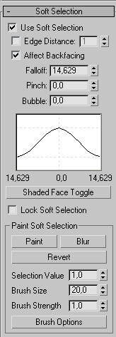
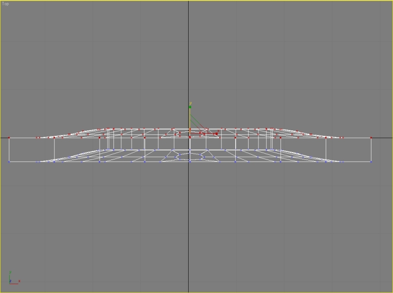
Select the segments, go to soft selection tick use soft selection and move the segments.
Make the back side flat by scaling the vertexes.
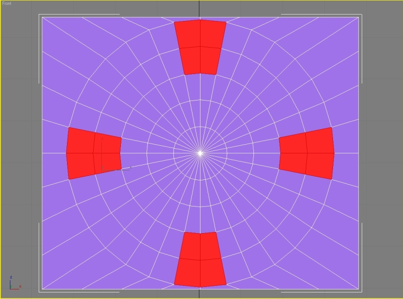
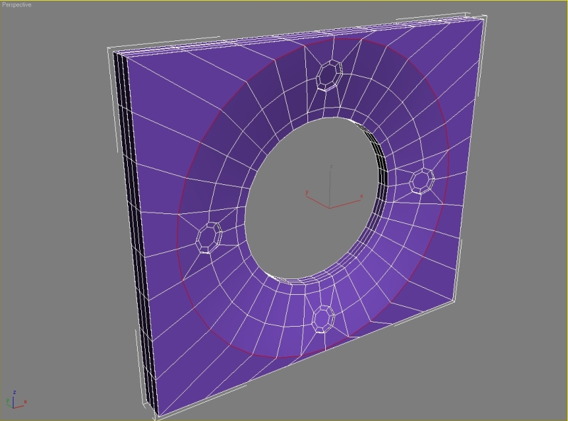
Select the polygons and hit extrude. Set extrusion height to -0,5. Also hit inset.
Select the edges and set crease to 1.
Step 10
Chamfer the other edges. Model the next buttons, everything is simple box modeling, chamfering and extruding.
The button with number 5 model with cylinders like you did the navigation button.
The button with star model from a simple box, chamfer the edge with amount 10, apply – 4, apply – 1,75.
Select the edges, hit connect with these parameters, then connect the vertexes.
Move the vertexes from the left viewport, remove these edges and connect the vertexes.
This is how should your button look like.
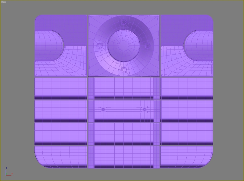
The last button model from a cylinder, delete one half, extrude and then just modify.
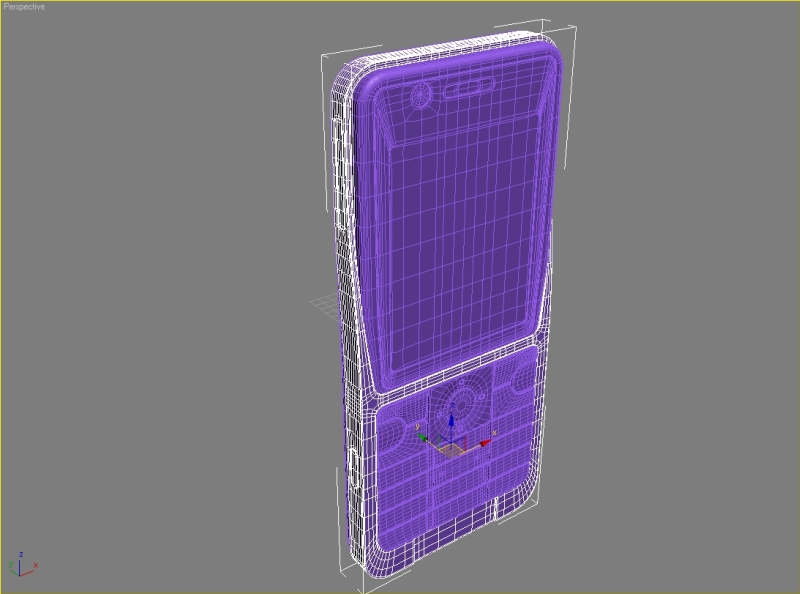
Your keyboard should look like this after all modifications.
Step 11
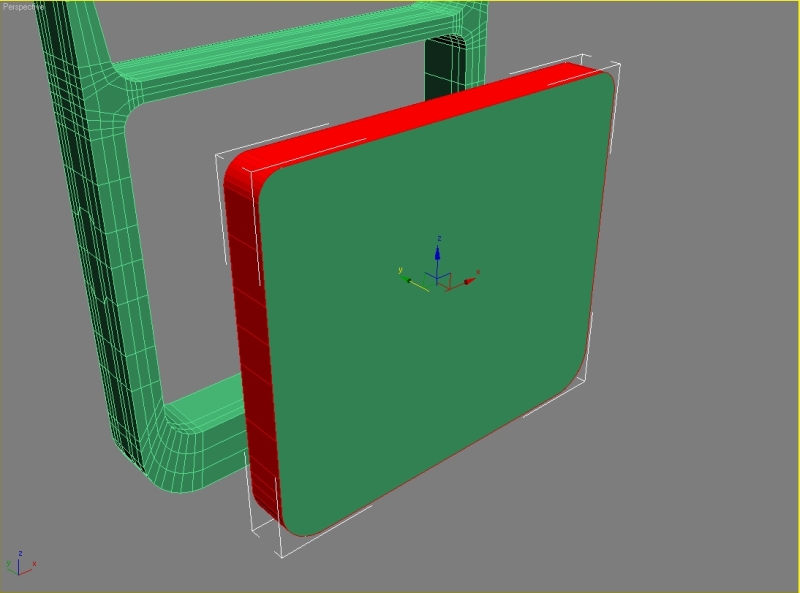
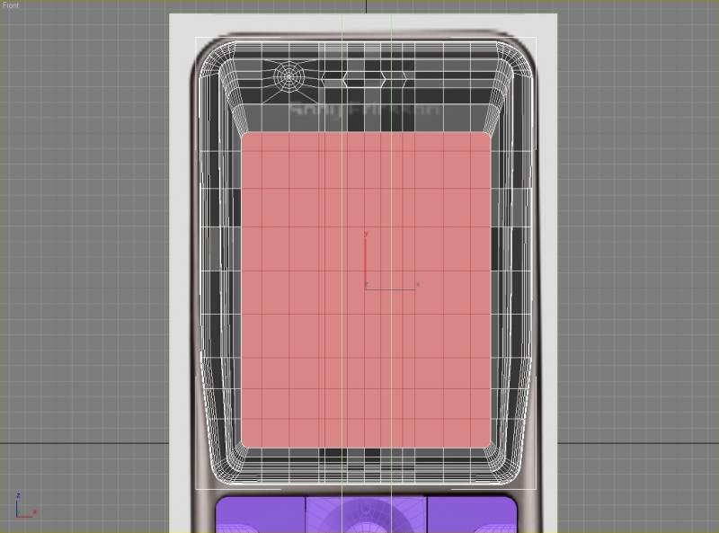
Start modeling the display from a box. Start with the inner box, then create two bigger boxes, attach and connect them.
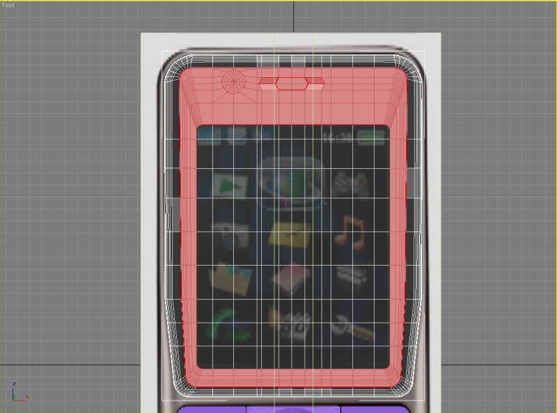
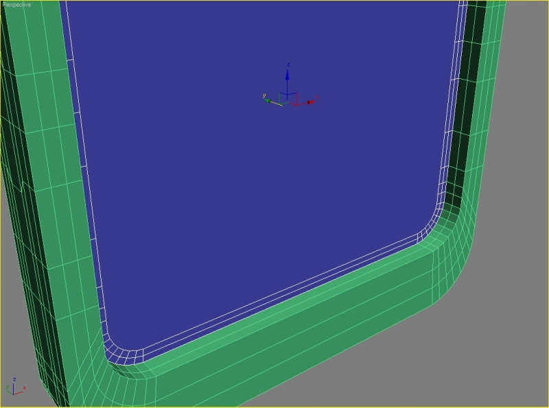
Step 12
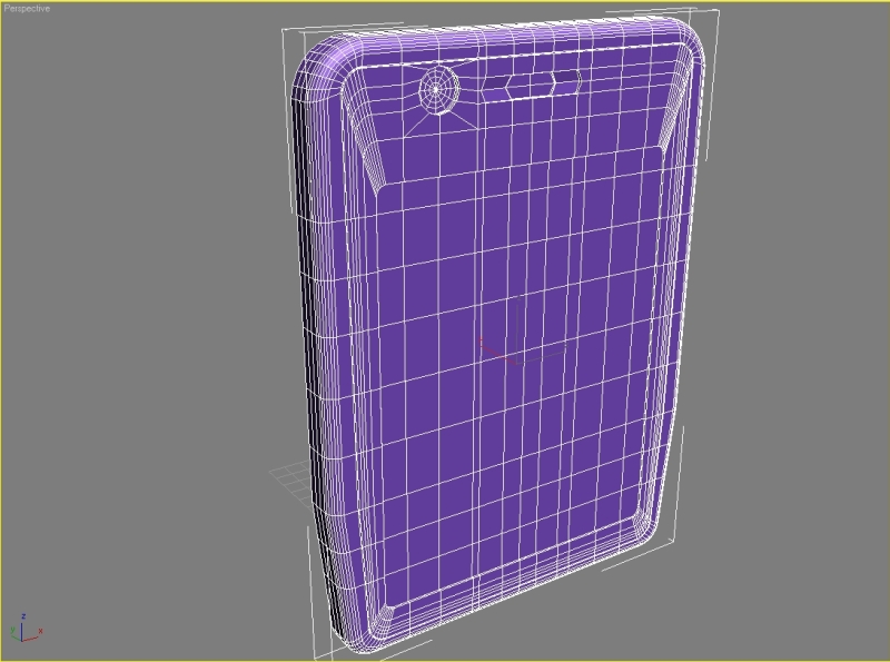
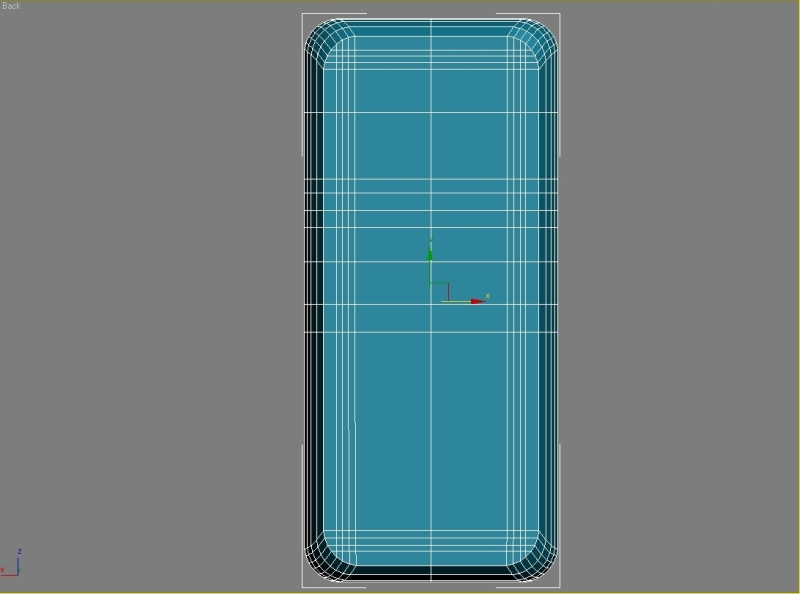
After this it’s just extruding, connecting, chamfering. Model the back side. Again it’s simple box modeling. Try to get result like this.
Step 13
Make the holes for reproductor with rectangles, connect the edges and delete the polygons.
Attach the rectangles to our back side, weld the verticles, extrude the polygons select the edges and set crease to 1.
Step 14
Model the camera from cylinder. Start making the connector.
Add some edges and extrude the polygons.
Step 15
Apply the Shell modificator to our back side and set Inner Amount to 1.
Step 16
We now need to Mirror our selection.
Step 17
Start modeling the logo. Create a tube with 21 sides and just extrude the segments untill you have result like this.
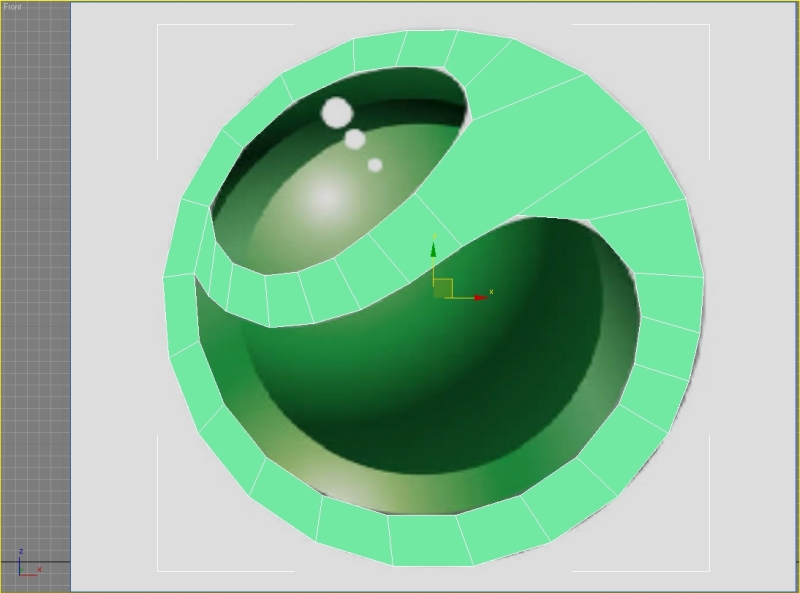
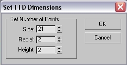
Apply the Shell modificator, convert it to editable poly and chamfer all the side segments. To bend the logo we need to use FFD(cyl) from the modifier list with these parameters.
Step 18
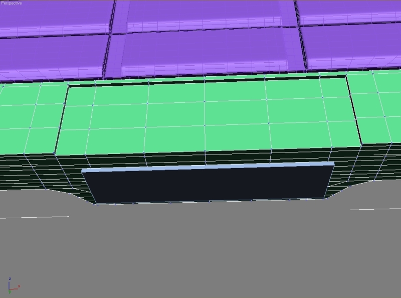
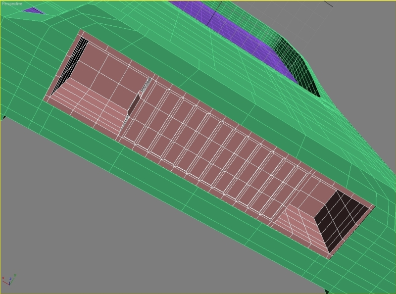
Start modeling the volume button and the cover for memory card.
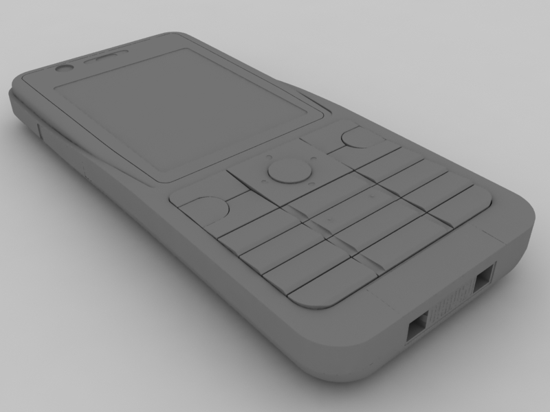
Final Result
 About the Author
My name is Jakub Pindroch. I was born in 1991 in a small town called Gelnica in the East Slovakia. I’m studying on high school in my home town. I always wanted to create my own models and scenes, so 4 years ago I started to learn 3ds max and since then I’m making models for my own use. After the study I’m hoping to work in game or movie industry.


About The Author
You might be interested in