The Making of Settled
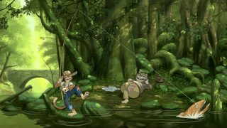
Hi all, for some of those who requested a tutorial from me, well here it is. In this tutorial I’m going to tell you how my scene called ‘Settled’ was made. I assume you have at least the basic knowledge and understanding of 3d.
|
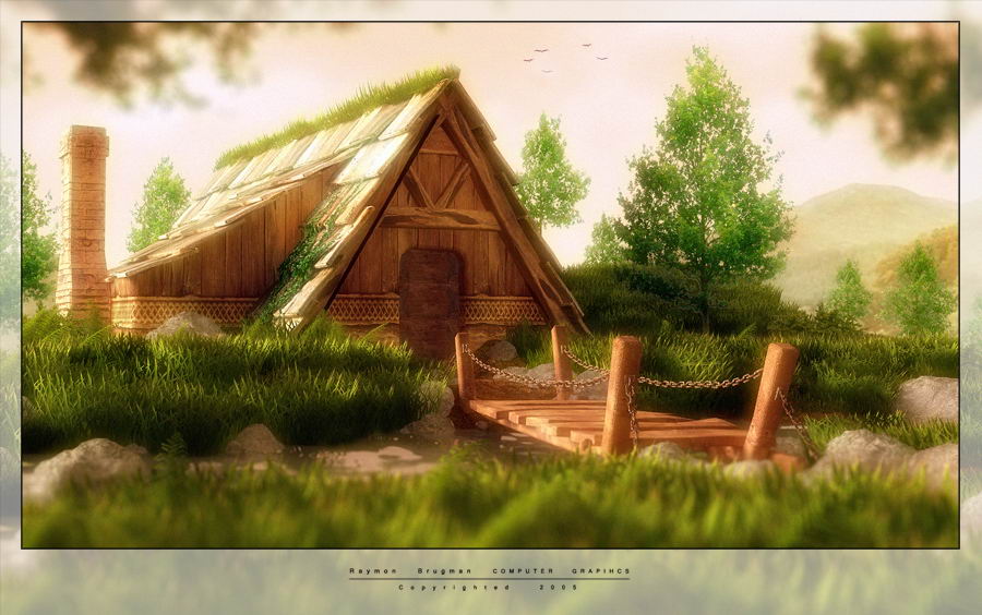
January 27, 2006 | Stryker Project Overview Settled FOREWORD: Hi all, for some of those who requested a tutorial from me, well here it is. In this tutorial I’m going to tell you how my scene called ‘Settled’ was made. I assume you have at least the basic knowledge and understanding of 3d. This tutorial is mainly focused on user’s 3ds max 7 (and its rendered with Vray Advanced) since I’m using this, but do not run away if you’re using Maya or some sort of other program, there are a few basics which will help you in your software package too.About this tutorial, it’s written in word (argh), and you will be able to zoom very close, to see and read the images in this document. GETTING STARTED:  Actually I didn’t start with any concept sketches or something; I just started creating the house used in my scene, not with any higher purpose in mind, just to test out my new work station. But sketching isn’t a bad idea at all, actually it’s even better when you’re making sketches before you start, remember: changing elements and so on in a 2d sketch is much easier and faster then 3d, so when you making mistakes you can easy correct it, while in 3d it could take up hours and hours. While working on the house, I thought, well I got the house, but where is it located, what’s the environment, and so on. So I was thinking how can I make a nice scene around it. Finally I got the idea to make a picture with lots of nature and a warm summer feeling to it, you could see it as the shire where no war will struck. To be honest, I never had done anything like this with so much nature around it (mainly because my old computer simply couldn’t handle it).I had no idea how to handle such great amount of nature since nature always provides huge amounts of polygons, so I choose for planes and opacity, later more about this.I had a composition in mind close to the one in the render. Actually I didn’t start with any concept sketches or something; I just started creating the house used in my scene, not with any higher purpose in mind, just to test out my new work station. But sketching isn’t a bad idea at all, actually it’s even better when you’re making sketches before you start, remember: changing elements and so on in a 2d sketch is much easier and faster then 3d, so when you making mistakes you can easy correct it, while in 3d it could take up hours and hours. While working on the house, I thought, well I got the house, but where is it located, what’s the environment, and so on. So I was thinking how can I make a nice scene around it. Finally I got the idea to make a picture with lots of nature and a warm summer feeling to it, you could see it as the shire where no war will struck. To be honest, I never had done anything like this with so much nature around it (mainly because my old computer simply couldn’t handle it).I had no idea how to handle such great amount of nature since nature always provides huge amounts of polygons, so I choose for planes and opacity, later more about this.I had a composition in mind close to the one in the render.
|
||
|
GETTING YOUR WORKSPACE PART: It’s very annoying when you don’t have a good workspace to work at, like a good desk, chair, and monitor, computer & sound setup. When I got my new computer this was something I paid lots of attention to. So I now have a desk that’s 115 cm deep and 215 cm wide, so everything has its own place, and I have space enough to rest my arms, type, work with a Wacom, drink, draw, and still have room for 2 monitors, 1 TV (out), pc, and a tuner . I absolutely can’t work without music, so I used a trick I got from my dad, to turn my music harder.A really handy thing to do is when you have external speakers hanging on your PC, amplified by a tuner, is simply to hang them on the ceiling, with chains, above the desk and monitors, this saves awesome amounts of space, but better, its reducing resonance produced by the speakers since they only hang on chains, you can then turn your music harder, without your mom vibrating off off the couch (not to hard offcourse, if you’ll just turn it to hard its going to happen anyway, that’s not to prevent).I recommend when you really want to go on in the film or media industry you get yourself a good computer, with a dual display setup. I worked 3 years on a Intel Pentium 3 1 gig Hz, with 512 Mb ram with one monitor. I could use 3ds max but I could not make scenes with tremendous amounts of polygons, GI, and complex scene setups, I taught myself the basics of 3d on this old feller just by browsing tutorials I found on the internet and the ones that come packed with 3ds max, so if your starting and you haven’t got a really good pc, don’t worry, then something like a good workstation is just something for in the future. This how my 3ds max interface nowadays looks with my dual display setup. When you want to make yourself a sort of home studio, improvisation is very important.
|
||

|
THE MODELING PART:
|
||

 The modeling is fairly simple, actually there’s nothing hard to it. It’s in fact all box modeling. The scene contains around 290.000 polygons(you can check your number of polygons with the polygon counter which is located in the utilities menu, more, there you find the polygon counter. You have several options which are very simple), and the real objects are mostly standard objects, like boxes (with 4x4x4 segments), which where edited with edit mesh, usually I just chamfered the edges, added some noise modifiers for the wooden parts of the building and bridges. When I had one wooden beam, I applied a UVW map on it so that I don’t have to do that when I’m al settled’ for texturing. The UVW is a standard 50x50x50 box, because all the goniometry are simply all cubes. On the left you see how I made a roof tile, but it’s the same method as wooden beam, they just have other proportions, as you can see a UVW map already applied. The bridge is build up mainly out of boxes, same method as the rest. The chains where made with a torus for every chain. The torussus where converted to chains as shown below. Also here I’ve applied an UVW map (box) to it, so that I don’t have to map 150 individual chains. The chains I now had, where placed by hand in position as shown below.

 Then there’s of course the ground. I used a plane of 80×80 segments. But then I had to stop, I was thinking of how to do all the detailed raising, of the edges around the house (this will make it look as if the house was there for like years, and the house sort of sunk in the ground), how did I raise the footpath precisely? I thought I encountered something that was a bit harder than I thought. But actually the answer lay much closer then I thought, and became fairly simple. I used a trick I once saw on the AutoDesk website. I applied an edit poly to the ground, and I unhide the house so I knew where it stood, and where to raise the ground. Now with the edit poly modifier, go to vertex and you’ll see a paint deformation pullout menu, roll it out. It should look like the picture on the left. Leave the push/pull direction settings as they are, and you now have a displacement brush sort of zBrush like (not as detailed, because it would simply cost to much polygons. With push/pull Value you can affect the impact the brush has on your model, + is raise, – is dig. Brush size speaks for itself I think. Brush strength is the pressure on the brush, how many times you have to paint the model over to get to yourself to the push/pull value. I painted the entire terrain, to create some random terrain. I also painted the footpath a bit higher, and decided to paint me a river to make it look more idealistic.

|
Finally I applied some more modifiers like meshsmooth with literations 1, FFD 4x4x4, and 2 noise modifiers each with their own size, seed and intensity . I also added a simple UVW map box which is set to fit. On the next page you can see how my modifier stack looks like. With this knowledge you can simply make very nice terrain. It’s just how many polygons and time you want to put in. The important thing is when you’re making terrain is to think what could have influenced it during the centuries lying there. To make the terrain a bit more convincing I added stones. The stones where made, with a pretty standard procedure. Take a geosphere (normal spheres aren’t very good because they don’t deform very convincing when a noise modifier is applied) and then apply a noise modifier on it, also a FFD 4x4x4 is quite handy to add, because you can deform the stone a bit more to your wishes. For the bigger stones I used 8 or 10 segments , for the smaller ones 4 or 3 . Also I applied an UVW map with box to the stones again, this is handy for later cloning as mentioned earlier before. You can see a stone sample on the right. Well that’s about it for the ground. |
 |
|||
|
ON TO THE VEGETATION: The vegetation was the hardest part in the project. How can you make millions of grass strands convincing, without blowing up you’re computer, or render times. The answer I choose was simply using opacity maps. In the first tests I did used grass planes , which where simply planes with a grass texture on it. This texture was composed with 3 or 4 different grass strands from the total textures 10 cd, so I’m sorry I can’t share the texture with you, because I think 3d total wouldn’t like it very much. But you can easily create some strands yourself, by picking some grass out of your garden, and scan them. When I finally got the texture set, I started duplicating my grass planes, but when I rendered my scene I saw this wasn’t working out with the lightning, since they are planes, they all looked very flat, and the light could not really interact with the grass. Sometimes it even made some awful bright spots on the planes when they faced a bit too much to the light. So I had to come up with an other way to fix this. Finally I got the idea to make cylinders and then apply a texture to it so it’smapping 360 degrees around it . The cylinders where made using planes with 3 length segments and 12 horizontal segments, it was bended 360 degrees in X axis, so it actual became a real plane. I also applied a FFD 3x3x 3 modifiers to taper the upper part of the cylinder (so it has that bended grass look when it all comes together).Finally and very imported this time is to really apply a UVW map set to cylinder (fit), when you forget it this time, hell brakes loose when you’re texturing it.I came up with the the texture you see below which was the same as the first, only horizontally copied a couple of times. I came out with the one below. ALPHA MAPS: The 3d total texture collections come with their own alpha maps, which provide transparency for the texture. But since my texture was modified, I had no alpha map for it, so I had to make one myself. This was the trick: In Photoshop make sure you’re texture is flattened (but save it first as a .psd). Then simply desaturate the texture, and then invert it. Be sure to desaturate it first, and then invert, or else it isn’t going to work. When it’s inverted adjust the brightness (make it brighter), then adjust the contrast which usually has to be more then the brightness, but be careful, you have to find a balance between them, or else the edges get jagged, and the opacity map will not fit correctly. When you have your opacity map save it as a new .jpg. Its very important to keep your textures well organized, and I usually make a new folder when I start a new project.
|
   |
|||

|
I usually have my textures named like this (with a grass texture as example): for color maps: Grass For bumb: Grass Bumb For opacity Grass Mask You now have yourself a alpha map or opacity map (just pick the term that suites you most =) ). And then, well you have tomake yourself a material (standard) in 3ds max (or your software package). For diffuse, select bitmap and then choose your color map (In bitmap controls I usually turn the blur setting to 0,01). For opacity select your opacity map the same way how you did for diffuse (also blur 0,01). You now can add a bumb map, for some more depth.This is pretty much the material for the grass.I almost forgot, but I cloned the grass materials 2 times and added a darker grass color map to the diffuse, and a lighter one. (this will create more randomness in the final result). Finally I cloned the grass cylinder 2 times, so I now have 3 grass cylinders with 3 grass materials, one dark, one middle and one lighter. Now the really fun part starts. For placing the grass I didn’t chose for scattering, since I knew I then would encounter many problems with the footpath, and the water. So I placed all grass cylinders manually. This really trains your nerves =). But rememberkeep the numbers of the cylinders with the 3 colors a bit equal, so one does not pop out of scene. The grass now interacted much and much better with the light. Since the bright side of the grass and the shadow side of the grass now faded over in each other. About the trees, they where made using the same method, only they where bended 45 degrees, and they had a higher bumb value since they are much larger this gives the trees a bit more depth. Also here I added some different color maps (lighter and darker ones) to make the scene look more organic. The plant climbing up the roof is not a real model, bit it’s a plane folded over the roof. The plane has 8 length segments and 4 width segments. Its folded over the roof tiles like shown on the right. The material for this plant is a tiny bit different, because the plane uses the VRayDisplacementMod. You can see my settings, object and material settings below. The map you see (klimop.jpg, is just a desatured version of the color map I used. I hope this is enough, or otherwise you can always mail me for any questions;). |
  |
|||

|
TEXTURING: Well about the texturing, this was actually a very easy part. I usually model something, and then texture it straight away, so I can see the final result, and when imperfect, adjust the model, or edit the texture (texture map, UVW, tiling and so on). When I have to do this when all objects are cloned, it would be very difficult. Since all objects had box UVW’s applied to them, it wasn’t to hard to texture. Actually all textures are from the total textures collection 14, with a few exceptions, so this was just a manner of picking the right combination of textures. The ground however was a bit harder. I didn’t chose for unwrapping, since I then only had some squares, but I really had to know where the river was, the footpath and the house. So the thing I did was just to make a snapshot from the top view port, with a strong light with shadows, giving the river and footpath shadows. This is how the scene was set up for the final snapshot. |
||


About The Author
You might be interested in