The Making of Upside-Down
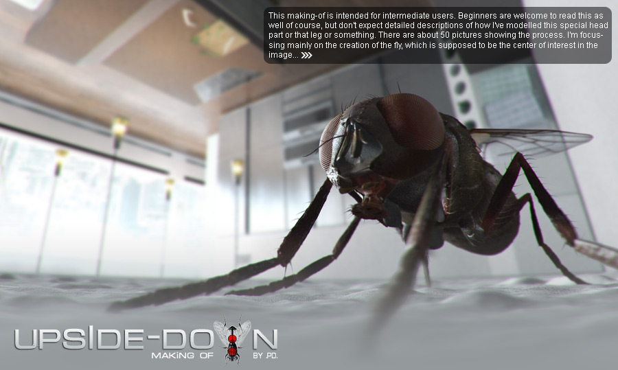
This making-of is intended for intermediate users. Beginners are welcome to read this as well of course, but don’t expect detailed descriptions of how I’ve modelled this special head part or that leg or something.
|
08 October, 2006 | Stryker The idea for the image came when was bored of seeing all those interior renderings everywhere. I really like good interior design, but I wanted to take a look at this from a new perspective. I also wanted to show something usual in an unusual way. So, I came up with the idea of showing a common housefly, from close-up, sitting somewhere in a kitchen. The idea develloped further into a fly sitting on the ceiling. This allowed me to turn the camera at 180° and therefor showing the fly in a normal position, but the kitchen ‘upside-down’. |
|
|
|
|||
 I’ve started modelling on the head. I began with a singe plane and went from there by extruding edges. |
 |
|||
 |
 |
|||
 I’ve added the eyes, using a sphere primitive which had to be tweaked slightly. |
 |
|||
 |
 |
|||
 |
 Still extruding edges… |
|||
 |
 I will create a morph target later, whith this ‘proboscis’ moved in. |
|||


 I’ve used cone primitives for those hairs, which got bent slightly. |
 The body started with a box primitive – smoothed with 1 iteration. |
|||
 Based on my reference files, I’ve painted the shapes of the ‘armor plates’ on the body. Those shapes were then extruded. |
 |
|||
 Some further detailing on the body itself. |
 And more armor plates. |
|||
 I’ve added a slit on the side,… |
 …put some hairs next to the slit and added the connections to the front legs. |
|||
 |
 Starting with the back part, again with a box primitive as a starting point. |
|||
 Further refining. |
 Using (renderable) splines to block in the legs. |
|||
 Converting the splines to epoly and shaping them into the desired form. |
 In top view I’ve created the wings, starting with a single plane and using the edge extrude method. |
|||
 I wanted to model those veins. So I had to change the topology with alot of cutting + welding. |
 Those edges were chamfered to gain some thicknes. To be able to smooth the wing, I had to create many new edges to get a nice topology(quads mostly). The shell modifier was used to give some thicknes to the wing itself. The polys between the ‘vein-edges’ were extruded somewhat to give the veins some height. |
|||
 This is the body-wing connection. |
 Click here to view big image The main modelling is done now. |
|||
 These are some hairs, which I’m going to put everywhere on the body. |
 To do this, I’ve used a script called ‘Mouseplanter’, written by Roger Hyde. It allows you to paint objects on the surface of others in a very intuitive way. Get it now! |
|||
 scary :) |
 Unwraping was very straightforward. I’ve used cylindrical and planar projections as a base and then had to tweak the UVs somewhat. |
|||
 I decided to rig this guy, to be able to pose him to some degree. The rig is very simple – just some bones and IK solvers. Since there don’t occur any deformations, I could simply link the leg parts and hairs to the bones. |
 Since the compound eyes are made of many tiny eyes I decided to rebuild them. I’ve used a geosphere this time. Read below why. |
|||
 Using the scatter compound object, I could put a tiny sphere on every vertex of the geosphere. The resulting alignment is exactly the same as in nature. The scatter object(including all those tiny spheres) was then baked as a height map to the geosphere. I could then use the height map, to displace the geosphere. |
 Click here to view big image This is the complete model with all displacement maps assigned. The maps were created in photoshop and are very simple. They consist of some noise layers, blured with different degrees, to create bumps with different sizes. I’ve handpainted a bump on the base of every hair, as well. I’m always creating displacement maps before any other texture maps, because they deform the mesh itself, which feels like I’m still modelling. Displacement maps are also great to use as a guid fore(or even as a part of) the color maps. |
|||
 Color maps were painted on top of the displacement maps – many dark brown and dark green blobs :) |
 Click here to view big image A render with all maps aplied in a simple studio set up. |
|||
 Click here to view big image Displacement close-up. |
 Some viewport grabs from the kitchen. Look at this cool porsche knife! |
|||
 I love this stool. Anyone knows, who designed it? Shoot me a mail! |
 Gaggenau rocks! |
|||
 This is the light setup. A large area light, right infront of the windows and 4 omnis. Notice the camera at the right. |
 The scene seen through the camera. |
|||
 Click here to view big image Kitchen render. I didn’t have to use super-high sample values, because everything is going to be blured. |
 Click here to view big image I had to render the fly in a seperate pass. The differences in scale made it somehow impossible for Max to render everything together. Everything went unbelievable slow, when I tried it. The fly measures about 1cm, while the entire room has about 7m. |
|||
 Click here to view big image Both passes combined together. The background is blured. There is also somd DoF on the fly pass. This helps to direct the focus to the flys head. I spend a lot of time finding the right camera position. This is important for a good composition. Since the head should be the focal point, I searched for lines the that can guide the viewers eye to the head. |
 Click here to view big image This is the final piece. I’ve added some lens distortion and decided to mirror the image. It might be just personal preference, but I think it does support the composition even more. In the western hemisphere, everyone is used to read from left to the right. And I guess this is true for looking at pictures as well. So in this case, the viewers eyes are entering the picture from the left and are guided directly to the flys head. |
|||
|
I hope you enjoyed this making-of. If you have further questions, don’t hesitate to contact me. 3DM models creation |
||||


About The Author
You might be interested in