DNA priority tutorial
INTRO
Hi everyone reading this overview about making-of my work “DNA_priority”. This overview is software-specific as I have used 3DsMAX and Rhinoceros for making a picture and Adobe Photoshop for post production but there are no limitations for other software users due to most of principals of production are the same. I will try to introduce to you how I made it. So there is my workflow below:
Before we start I want you to know that some techniques and solutions that I used can come in sight as something incorrect and maybe strange but anyway I will explain the process as it is. 3D as I see is a some kind of art and there are no limits and ultimate rules after all. So I hope you will like the article.
DECISIONS
Generally before the project have to be started it is important to decide to yourself what your work will look like. I mean the mood and impressions of the final image. I think it is not a good idea to change your mind about the style in the middle of the process. But if you sure that your new style or mood is better than you are workin on, so do it – change everything. In this case during the process I have spent a lot of time sitting in front of my monitor and just look “inside” view ports because I have no idea how to make it more expressive. So if I didn’t like the result I delete all the files of modifications.
>>>Tip: pressing SHIFT+DEL is a best way to make your work better.
If you don’t like what you do, who will? :)
So before I started I decide to show a symbiosis and make the picture non-stylised and realistic as I can. And I thought that filling the scene with abstract and incomprehensibleobjects will solve a good fake effect (as for me I like artworks that fake me out and looks real.As one of my teachers said:”You know that it is fake, but you don’t know where it is”).So all theese was my guidance in the process and I followed it.
>>>Tip: If you know what you want the half of the process is finished.
MODELING
So the next step is modeling. All the geometry in the scene was created with NURBS and POLY with NURMS subdivision techniques. The mesh is quiet simple,so I don’t see any reasons for deep explanation of modeling but however maybe someone will find it useful if a few samples will be shown…
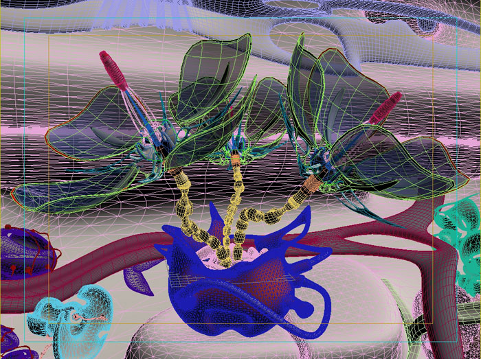
This is an overall mesh view at the end of modeling process. Well… Actually when I see this and the final image I arrive at a conclusion that the mesh is “overloaded”. In my oppinion the rule “you shouldn’t model it if nobody can see it” is completely correct. But sometimes it is impossible to know what does the final image look like. And in this case exact positions of objects wasn’t determined yet. But anyway it’s always better to realise a proper distribution of mesh density: the closer the object to camera the higher density should be provided and vice versa. Of course this is not a strong principle especially when you are going to use effects (DOF for example) but it will sufficiently increase the perfomance and rendering speed.
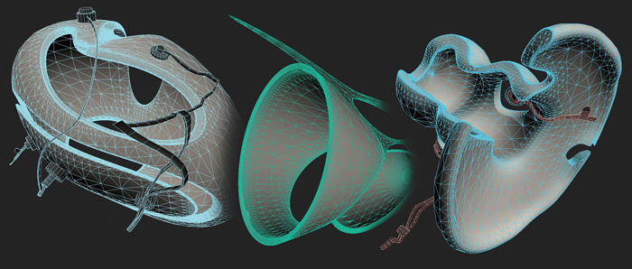
OK. To create these objects (except of wires and other small details) I’ve used Rhinoceros.I found this software very useful when I need to create smooth surfaces that do not require of “clean” meshes and normals. As you see all of this objects consist of triangles withdensity distributed regulary over the surface depending on it’s curvature.
>>>Tip: Such a geometry is still editable but Idon’think this is a good idea to do it directly.So it would be logical if we have final meshes inNURBS modeling output.
Rhinoceros has many powerful tools and is very flexible in modeling. Except of allexported meshes contain UV coords (in some cases it really helps in mapping). In additionit brings a lot of fun. :)
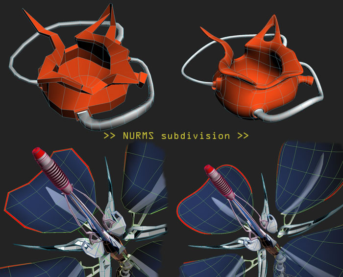
This figure shows some of geometry was made in 3DsMAX. So everything is very simple as you see.There are input meshes on the left side and final meshes after NURMS subdivision applied to iton the right side. Priorly it is Editable poly with subdivision surface turned on but thereare no global difference if MSmooth modifier would be applied to low-poly later.After completing a low-poly model it is very helpful for mapping to apply polygon ID’s and assign Milti/Sub-Object material with different diffuse color attribute. And besides it helps to distinguish objectsin viewports to get a proper composition.
>>>Tip: To meshes with extremely high number of polygons on output it’s better to apply different subdivision values for viewport and render due to high valuesfor viewport may sufficiently slow down VGA adapter perfomance (for figure abovethose values are the same with isoline display option turned on).
After all the geometry is completed and have a proper position in the sceneI have started the next step “lighting”.
LIGHTING
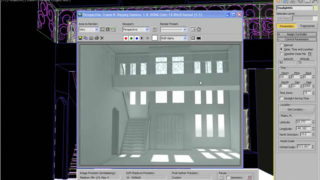
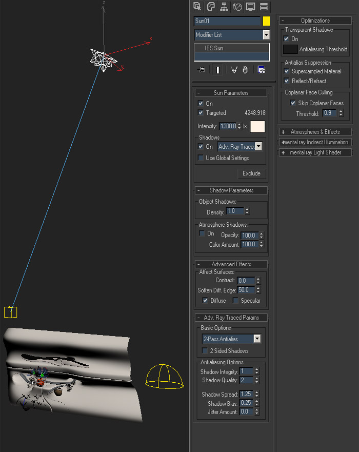
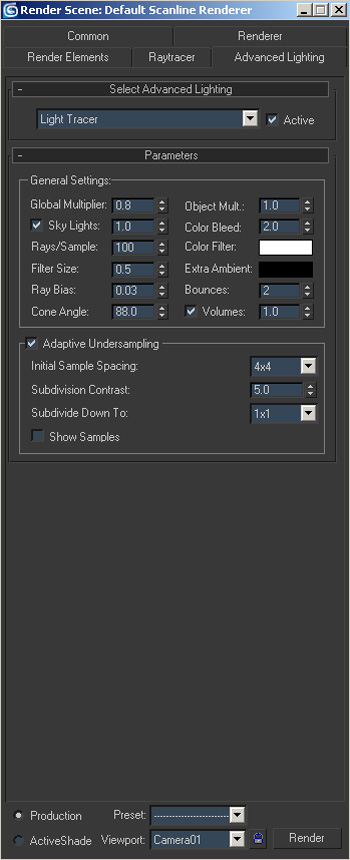
Talking about lighting it is necessarily to bear in mind that everything should be in conjunction withrenderer you have chosen earlier. This time I chose Light Tracer as Advanced Lighting (Default Scanline Renderer). So due to this I am able to use Skylight and IES Sun and don’t have to worry that something would be wrong with rendering. You can see lights positions on the figure below with IES Sunparameters.
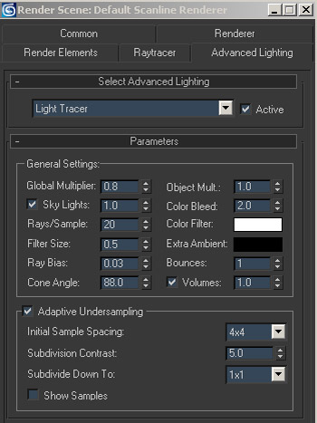
As for Skylight I left it’s params by default. After some renderer adjustments that’s what I hadon output:
Ofcourse it is only a first steps to finat rendering but it is necessary to decide an overall light ina scene before texturing and then calibrate textures to lighting. As you see it is time to go on with texturing.
TEXTURING
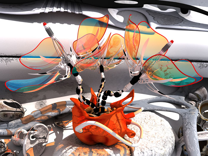
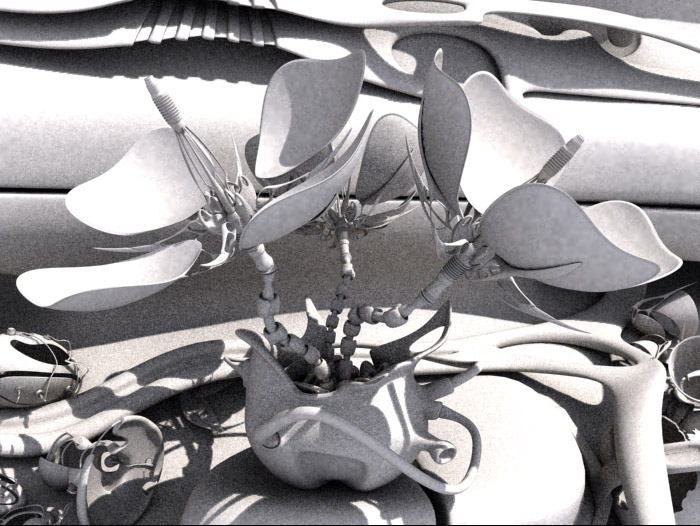
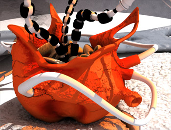
OK. Now it’s time to go on with texturing. In this part I’m gonna try to introduse to you how I make textures for most significant objects in a scene. I’m realy sorry for not every object would be touched but it is noy necessary as I’ve used the same texturing technique for almost every object. For clarity I show the picture that was made before postproduction to see all the textures more pure.
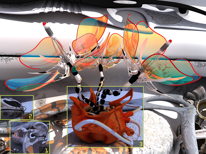
So the object signed by number “1”.
As I said earlier NURBS surfaces have it’s own UV coords that aren’t editable during the modeling process. After I have exported this model to mesh and apply UVW Unwrap modifier to itI became some frustrated… Just look at that:
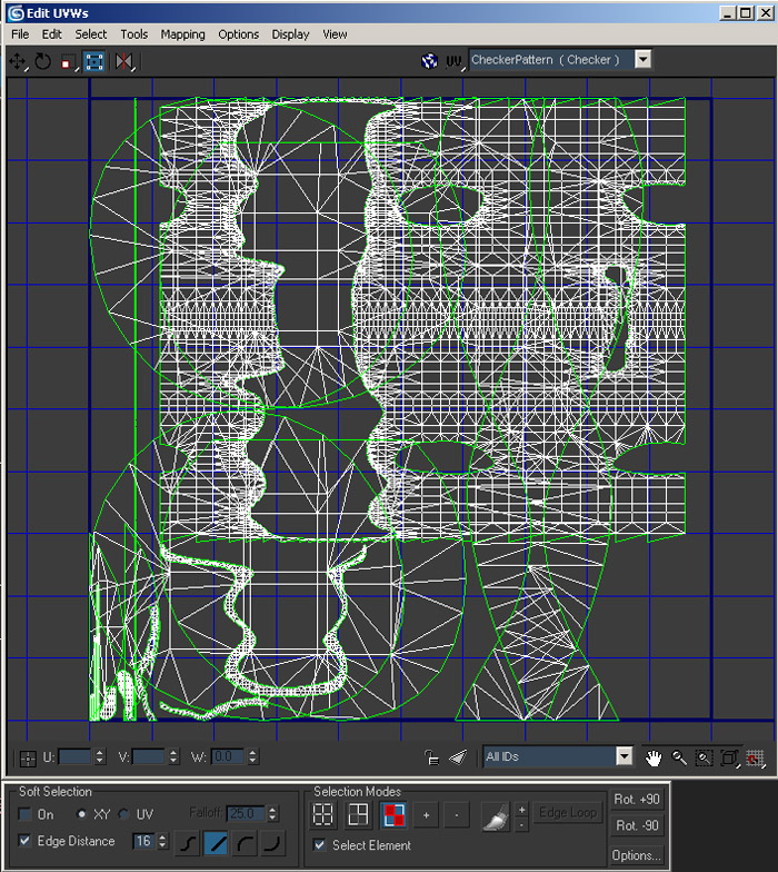
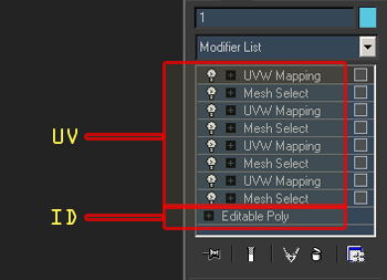
Ofcourse it’s everything OK about the software because all the coords are generated depending tomodeling coherence but I have no time to determine “what is what” and after thisscale the UV’s to match real proportions and weld vertexes in Edit UVWs mode (with reference to Unwrap UVW modifier)to provide seamless of the texture if needed. A lot of work, isn’t it?! So I used another way. I devidedmy model by a number of parts and apply different ID’s to each of them. Then using Mesh Select (by ID)and UVW Mapping modifiers to every part of it. I set the same channel for all of UVW Mapping modifiers in the stack that displayed below:
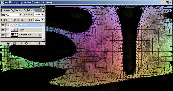
When everything was assigned i’ve started with setting up material. After assigning Multi/Sub-Object material the next step was pure (I mean base) diffuse color. it doesn’t matter what is it exacly but it’s important that it is the same in all of Sub-Materials diffuse color attribute to avoid of color difference along the object. What is it all for? The point of it is in ability to paint the textures we need withoutwearisome manipulations with UVW coords as we have the high-poly mesh on output. Then… Very useful plug-in “Texporter” written by Cuneyt Ozdas and Sinan Vural realy helped me to render UVW template.I rendered every ID of the material and then open it in Adobe Photoshop. There is one of IDs on the image below:
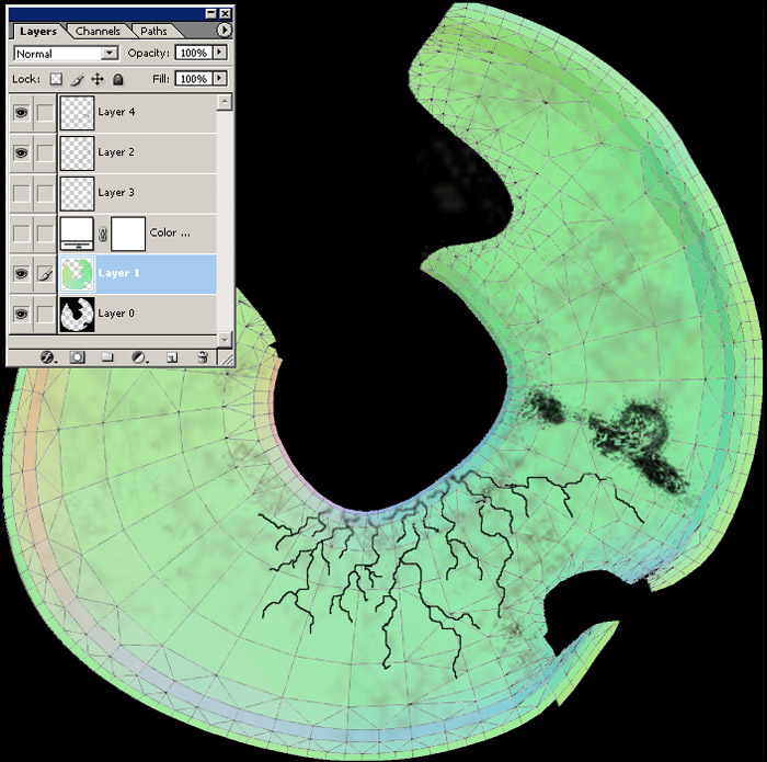
Then i made a couple of new layers and start to paint textures. As you see it is some dirt, scratches and dust. After completing the texture I save it as PSD format and returned to Material editor. As I have more than one layer as diffuse so I used composite map for it in editor. Then I just put every layer from bottom to top. There is an expanded part of material tree on the next figure showing settings I used.
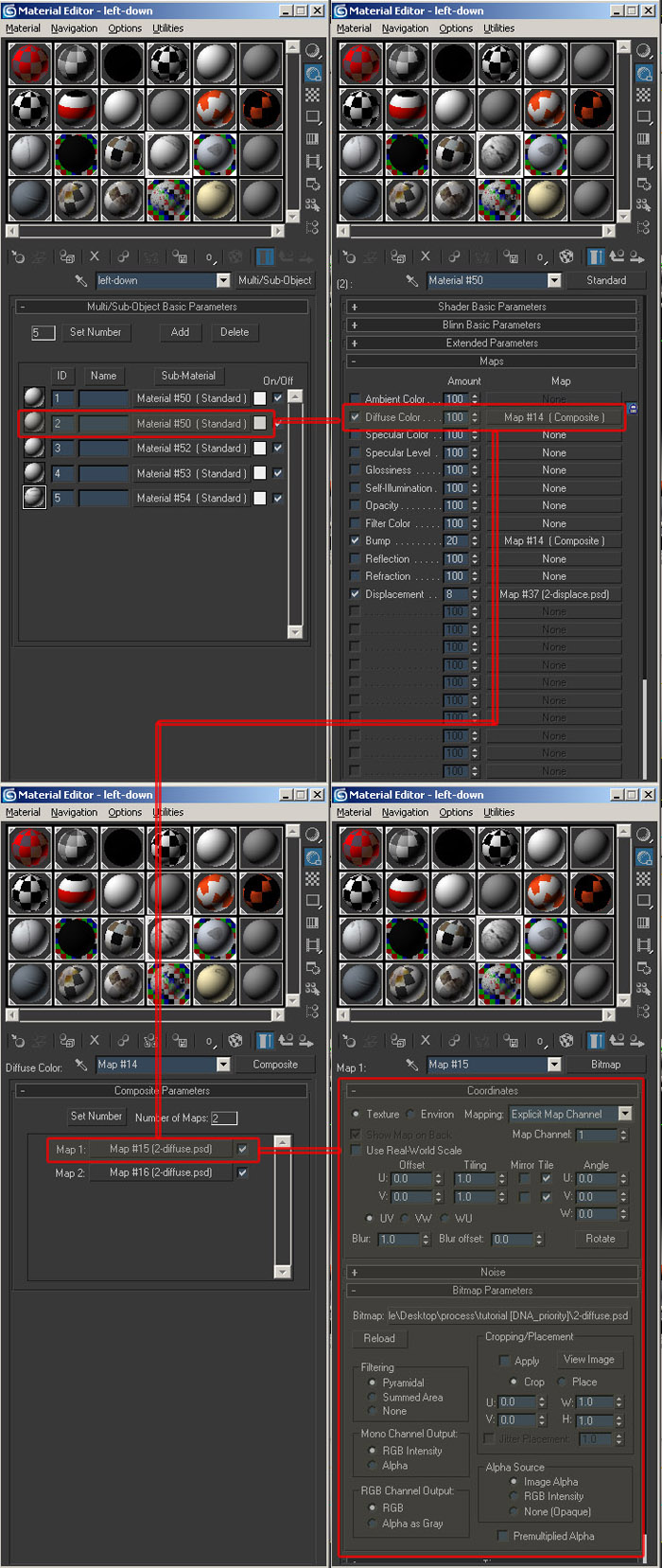
Ofcourse it doesn’t matter what texture attribute it will be, diffuse or displace and etc.The main idea is in completely free texture making process.
>>>Tip: PSD is very powerfull and flexible format to use it intexture making. You can manage and change layers anytime you need.But it takes a lot of memory.
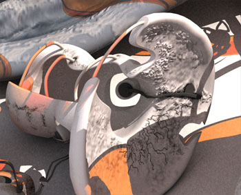
OK. Let’s go on… The object signed by number “2”.
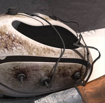
As I said everything is similar to previous technique. I have used PSD format again with its ability to store an alpha-channel. Making the texture below:
>>>Tip: If you use PSD format with more than one layer (in my opinion only in this case it is logical) it is always a good idea to check up layer visibility before using it as input to texture in cases when you gonna use collapsed layers.
The object number “3”.
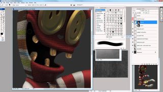
This object is of great importance in a scene and takes a great attention. So I make a higher resolution for texture rather than for others. I will show only a part of it:
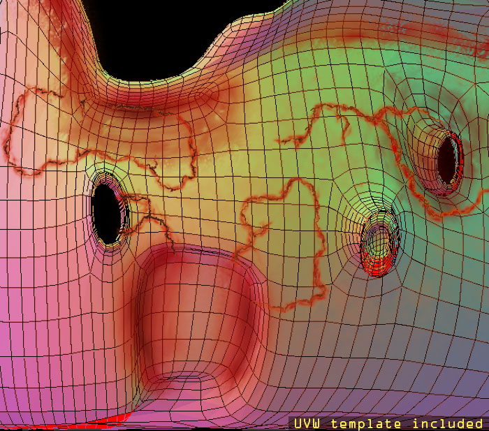
I used “Texporter” plug-in to render UVW template for guide purposes…
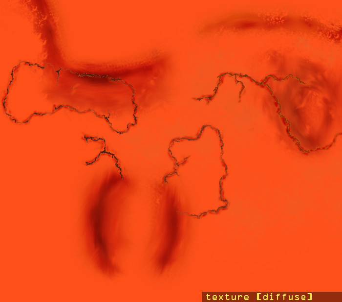
Unfortunatelly not everyone of us have pen tablet for drawing (and me too). And this texture was created with usual mouse. It brought me some difficulties to paint scratches but interesting. In my opinion it is very important to have a right humour to bring the right mood and maybe “feel” the texture. By the way as I remember I was making a sound like “schhhhrrr” when i painted it :) Everyone got his own way, you know ;)
RENDERING
After textures calibration and assigning materials I’ve started with final rendering. The final render params set up:
I rendered this image for printing with WXH = 5511X4133 (in pixels). It was veeeery long time for the process (about 6 full days) and my PC was very hot :)
>>>Tip: never torture your PC or it will…
And the final render:

Well… Actually I thought that everything is as I want but something was wrong and I didn’t know what it is exacly. If you return to “decisions” part of this article you can see that the main idea is symbiosis. So the first eye drop should be to the flowers and flowerpot. But when i look at the image the environment attracts a large amount of attention and I “don’t see” the main part. And that’s why I’ve decided to make the next part of my workflow post production more complex rather than levels and other adjustments… Uffff.. this is not the end… ;)
POSTPRODUCTION
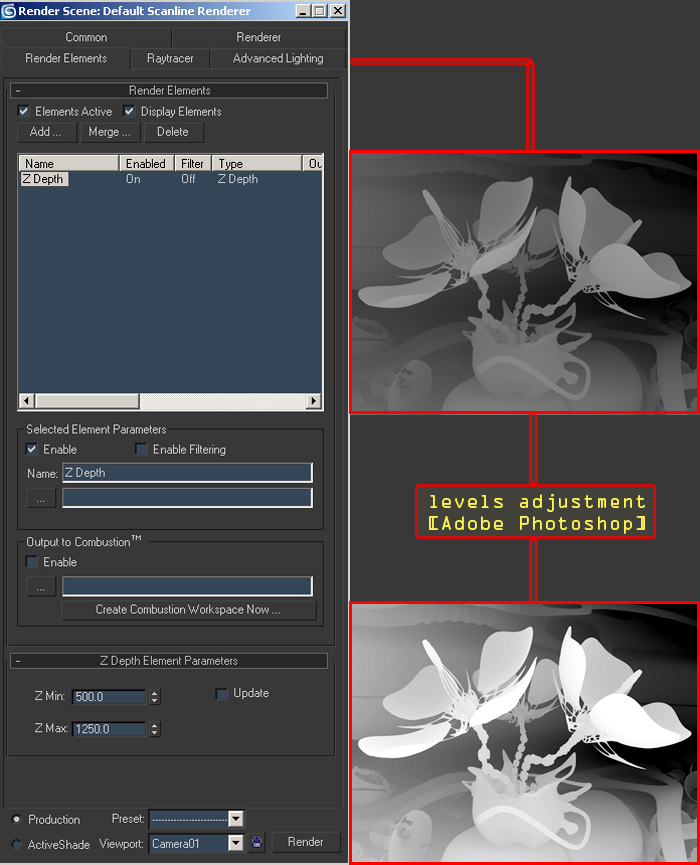
All the postproduction process was made in Adobe Photoshop 8.0 First of all I decided to apply Depth of Field lens effect with using of Z Depth map as sourse. On the image below you see how I rendered Z Depth map and applied levels in Adobe Photoshop to it:
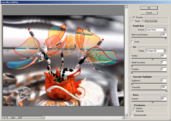
Then I use the DOF effect (Lens Blur filter in Adobe PS) with Z Depth as mask:
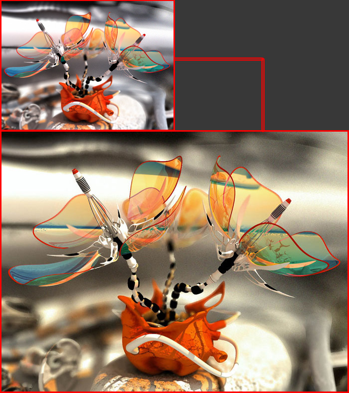
After appluying the effect I’ve just discard my mask. And the final step was Levels, Brightness/Contrast, Photo Filter and other standart adjustments. So….:) The final image:
Thanks for reading me and till next time.


About The Author
You might be interested in