
Creating those darn door seams by Daniel Buck
To start off with, I assume that you know basic knowledge of 3dMax. I am using 3dMax5, and I am not sure how this will translate over to any previous versions. Anyway, on to the tutorial. All the instructions refer to the pictures below the text.
First, we will create what will be the side or “body” of a car. In the front viewport, create a plane with a length of 50 and a width of 100, and name it body.

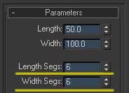
Now go to the modify tab, and change the length and width segments to 6 so we have a bit more geometry to work with. Change the object to an editable poly and click on vertex mode.
In the left window, move the top set of vertexes down and over so that they look like the pictures below.

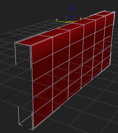
Now in the front viewport, click on polygon mode and select the polygons showed in the picture below.
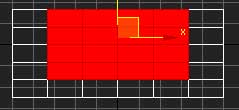
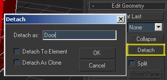
and click detach, naming the new object “door”.
Get out of polygon mode and select the door object, and go into vertex mode and select the set of vertexes on the right side and move them -.5 units on the x axis. On your own car project, you may need to specify a different value, but if you are following this tutorial exactly, these numbers will work.
IF you are doing your own car project, move these vertexes to however wide the crack needs to be. I AM EXAGGERATING the gap for this tutorial, purely to make the results easier to see.
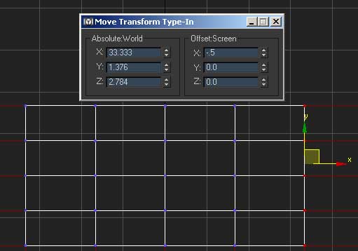
Do the same for the left side, only move the vertices in a positive direction, not negative.
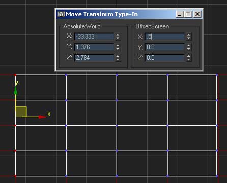
And the same for the bottom set, only move them .5 units on the y axis.
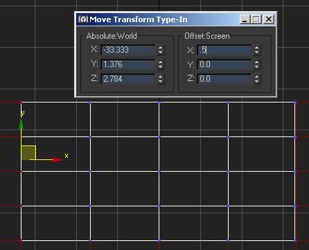
Now in edge mode select all the surrounding edges except the top ones shown in the picture below.
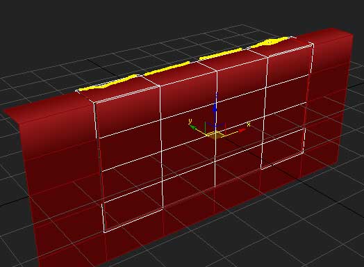
and chamfer them .5 units. You will notice the chamfer value is the same value we used when we moved the vertices. I have found that if these values are the same, it will work out nicely.

Now select the very outside edges just as before…
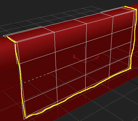
except the little edges on top, don’t accidentally select this one, it is so small that you might not even know you have it selected. Check and make sure. There is another small one on the other side as well, don’t select it either.
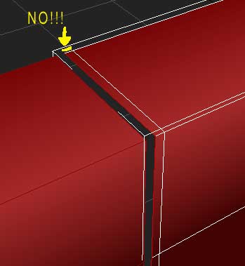
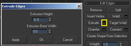
Now extrude with a height value of -0.1 and a base width of 0, which will give our door a nice crisp edge instead of a very rounded cartoony look.
Add some irritations to the mesh…
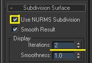
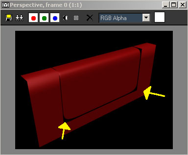
and render. See how the corners are rounded? Sweet eh? No work at all :)
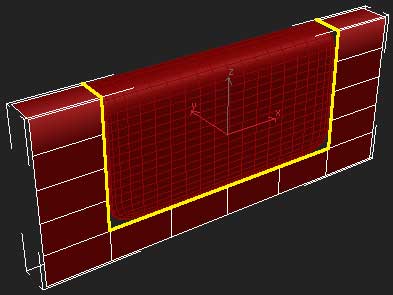
Now continue the same process you did on the door, to the body of the mesh on the shown edges.
and render. But WAIT!! those corners looks UGLY!!
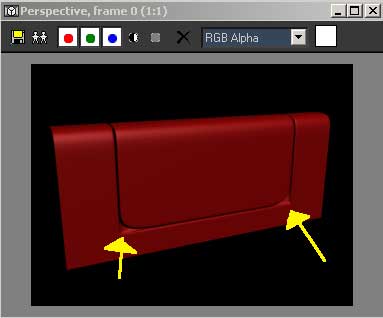
Yes I know, here is how we fix it :) Zoom in to one of the selected areas in the front viewport (they are the same, you will need to do the next 3 steps 2 times, one for each corner.
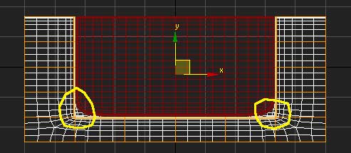
Select the 2 vertexes shown below,
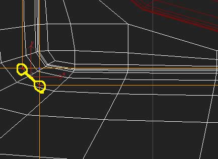
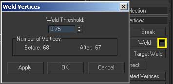
and weld. Move the threshold up till they snap. It should be about .70-.75 when they snap. (if you are working on a different project on a different scale, the threshold will need to be different)
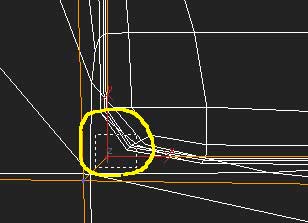
Next, MARQUEE select around the remaining vertex. It’s not just one vertex, it’s actually 3, so you will need to marquee select them. (hehe, they are hiding from you!) Now weld them as well.
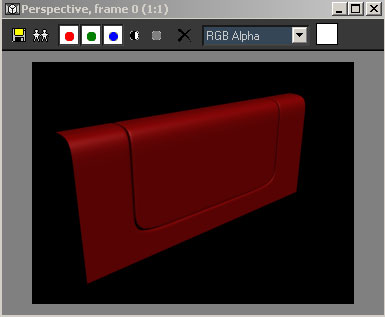
Do the same for the other side, and render! Presto! No work at all :)
Please take this tutorial as information, not for the exact steps taken while working on your own car project. Though you may very well end up using some of the same exact steps for your own car, each car is different and will require different values of extrusion and what not, but these are the basic steps that I use to create my cars.
