Ford Focus Tutorial Series by Alex: Part 2
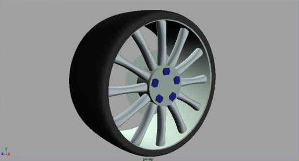
Hi everyone and welcome to part 2 of how to model a Ford Focus. We will be starting out simple by creating wheels for the car. Well actually we will be creating two different designs. This just to show you how easy it is to do and how you can make any design you want in a matter of minutes. Well let’s start.
1. Open Maya and open the scene we set up in part 1.
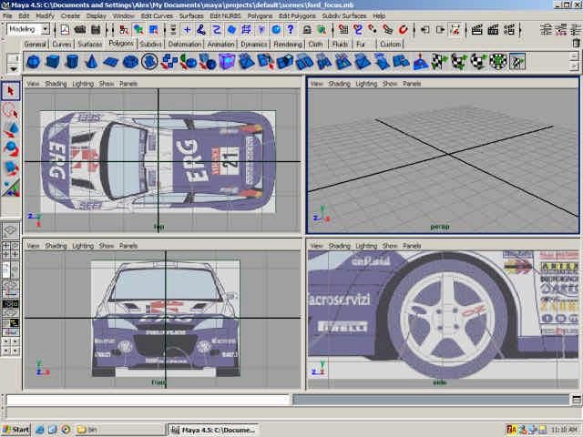
2. Create a profile cure using EP Curve Tool and place it accordingly to the image.
3. Now in side view move the pivot of the curve (press insert to move the pivot and insert again to go back to normal mode), so the pivot is in the centre of the wheel.
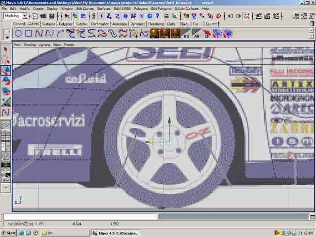
4. Now revolve the surface (Surfaces > Revolve) in the X axis and you should have
something like this.
5. Since the car that we are making ultimately is going to end up as Sub-D convert the
created surface to Sub-D (Modify > Convert > NURBS to Sub-D0
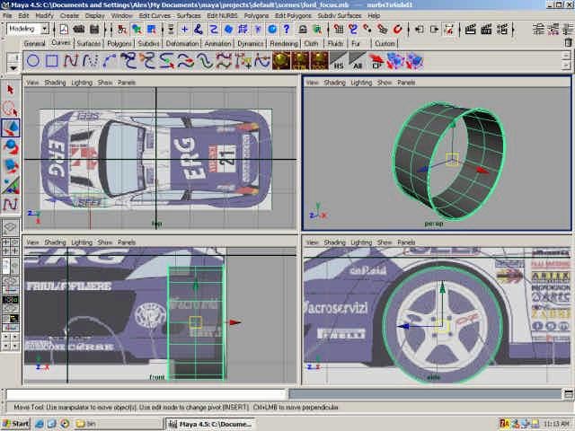
6. Now create a NURBS cylinder and rotate it 90 in the Z axis and place it like so.
10. To create the “lid” for the cylinder select the end isosparm (picture below) and offset
it as a curve (Edit Curve > Offset Curve) with offset set to 0.
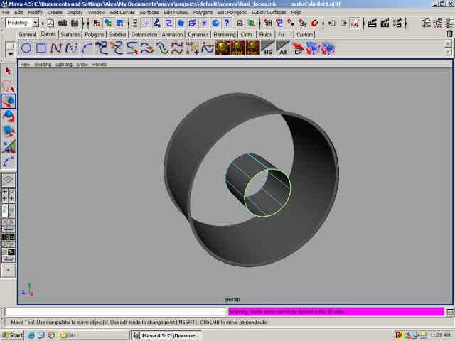
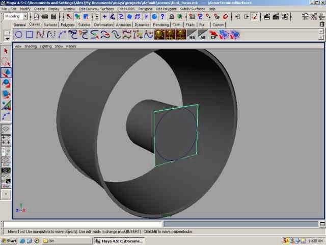
11. Now select that curve we just made and the go to Surfaces > Planar and you should
get a circle surface. Now the picture below has a square but these are just my Maya
settings. When you actually render it, it’s a proper circle. So don’t worry. :)
12. Now for the pikes. Create a polygon cylinder and move it and scale it according to the picture.
13. Increase the subdivisions across height to 6 (Channel Box).
14. Select the vertices row by row and scale them to for a shape as you see below (more
or less).
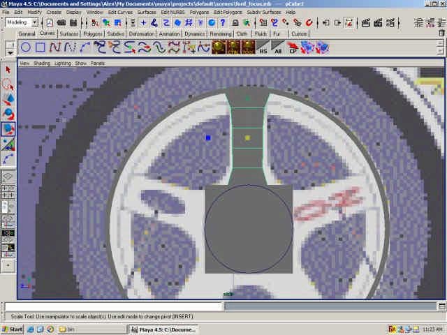
14. Now convert to Sub-D.
15. Now just tweak the vertices (I prefer the polygon mode).
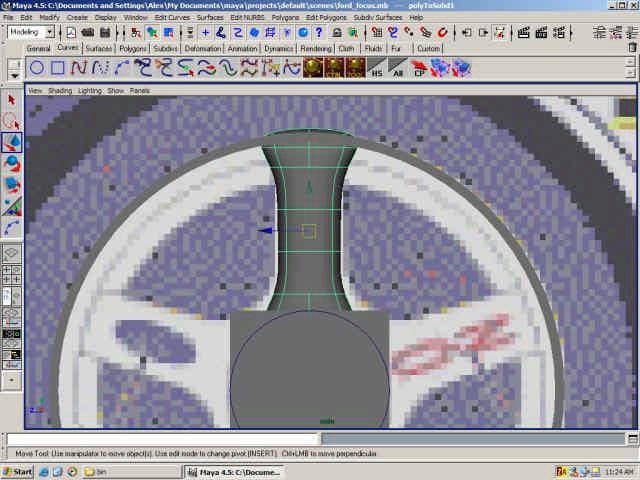
16. Now move the pivot into the center of the wheel.
17. If you have read my other tutorial you would have probably guessed that this is for duplicating the pikes. If you haven’t all we are going to do is set some settings in Maya so it automatically rotates them and places them where we need them. So go to Edit > Duplicate options and set ROTATE X 72 and switch on INSTANCE and set NUMBER OF COPIES to 4. Why are we rotating 72? Because if you divide 360 by 5 we get 72.
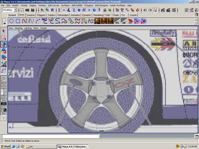
What we have so far.
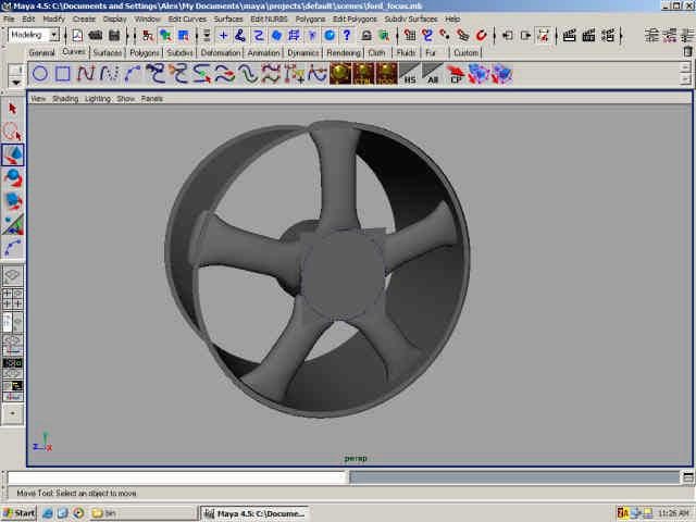
17. To create the bolts just create a poly cube and move and scale it like below.
18. Increase the subdivisions across height to 2 and scale the new vertices to form a shape of a bolt head. No need to model the actual screw because no-one is going to see it. By you can if you want :). Hint: use the twist deformer.
19. Center the pivot again and rotate with the same settings.
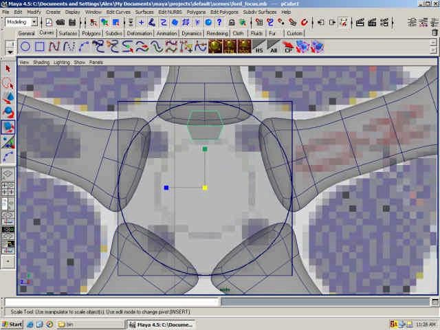
20. To make the pikes a bit more attractive select the edges as show below and go to Subdiv Surfaces > Full Crease Edge/Vertex.
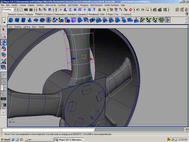
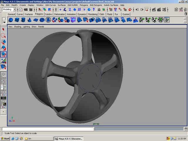
21. To create a brake disk simply loft two curves like below.
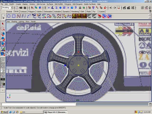
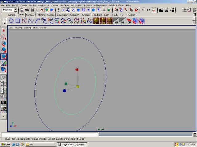
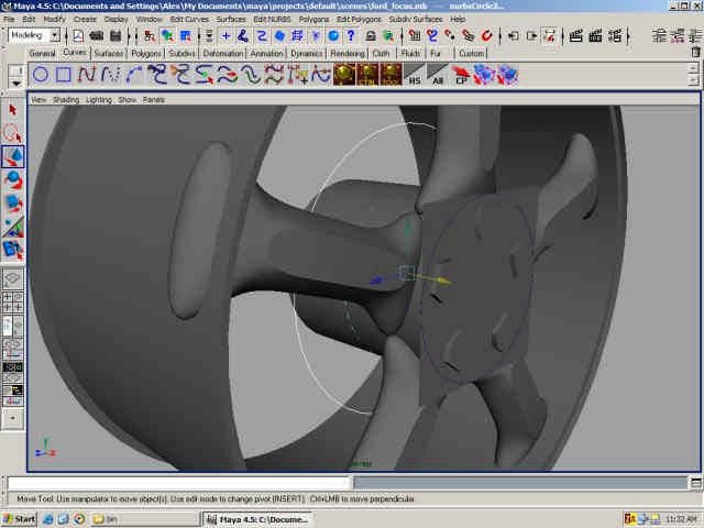
As you go along convert surfaces to Sub-D. As you see in the wire below the mesh is much cleaner. Later on the mesh is going to be pretty heave so it’s good to have nice and clean wires.
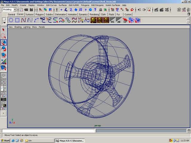
22. Now to create the treads. Create a poly plane and move and scale it like below.
23. Increase the subdivision along height to 7.
24. Scale the vertices like below.
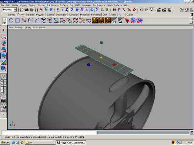
25. Select the three faces and go to Edit Polygons > Extrude Face (default settings). The move the extruded faces up.
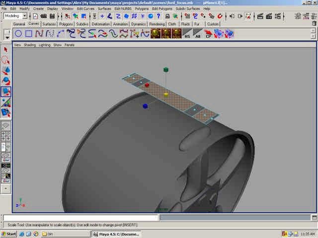
26. By extracting the outer two edges a few times create the surface like below (very ease just select the outer two edges, extract them and move them down to the rim of the wheel).
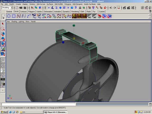
27. Now put the pivot into the middle of the wheel and rotate using following settings: ROTATE X 6, NUMBER OF COPIES 59. You then get sort of a thread. I don’t prefer this method but poly gurus might. Later on I’ll show you the other way. Convert it to Sub- D or combine them if you like. Or group.
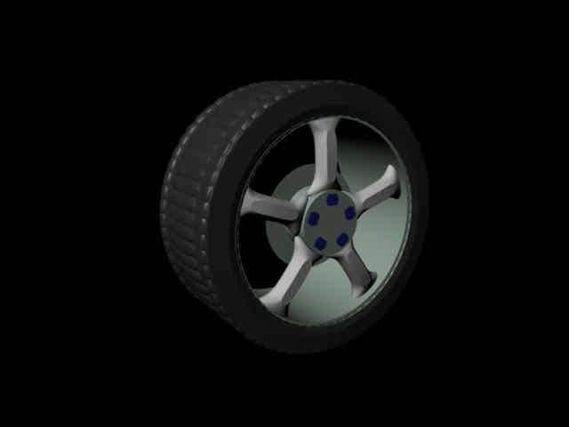
Version 1 finished!
- Version 2
1. Delete the poly tread and the pikes.
2. Create a curve like below and scale and place according to the ref planes.
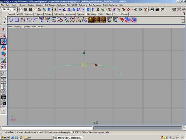
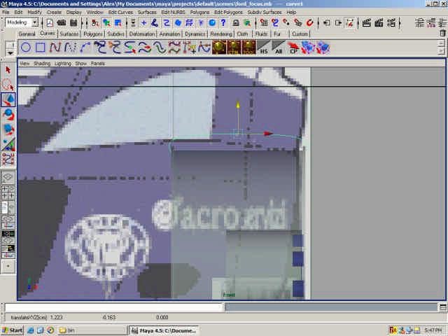
3. Now move the pivot of the curve into the middle of the wheel and revolve. Much nicer all we need now is a nice map texture. :)
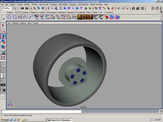
4. To create a different set of pikes just create another poly cylinder and scale it and moveas below. Notice it much thinner.
5. Increase the subdivisions and scale the vertices as below.
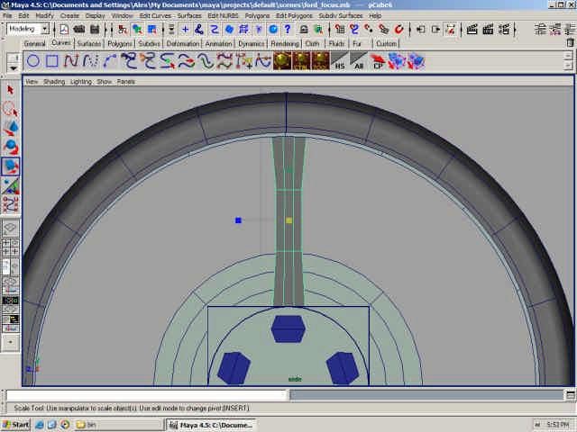
6. Now select the middle faces and move them out a bit.
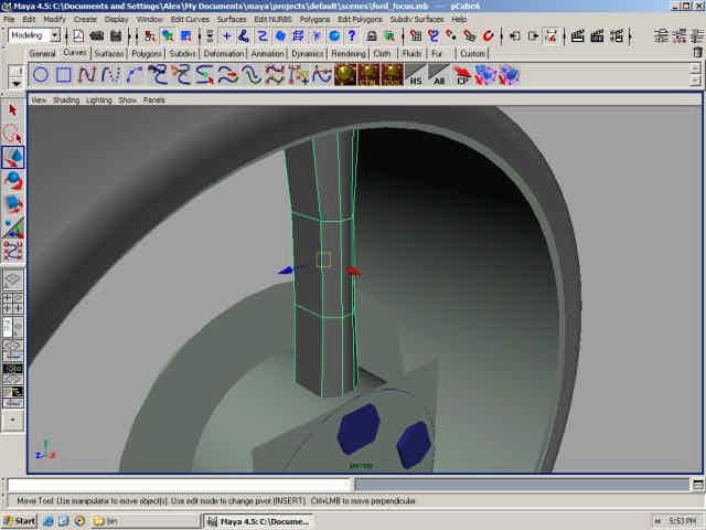
7. Add a bit more shape in the front view.
8. Convert to Sub-D and the select the middle edges.
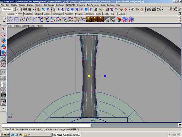
9. With the edges selected go to Subdiv Surfaces > Full Crease Edge/Vertex. This adds a bit more variety to the shape.
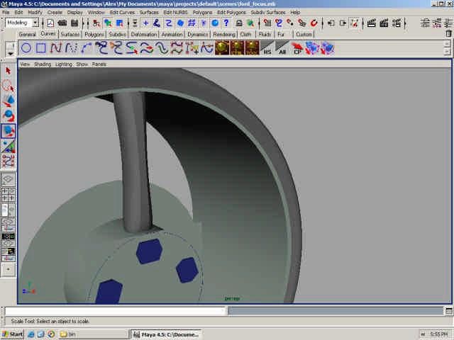
10. Center the pivot again and duplicate with following options: ROTATE X 30 and NUMBER OF COPIES 11.
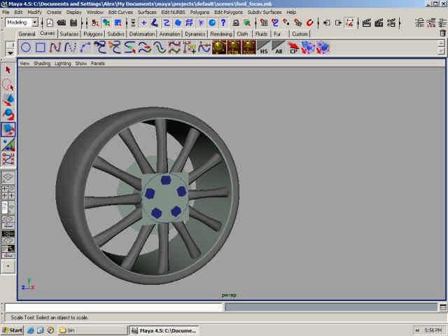
Done!
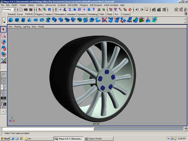
You see how easy it is? You can modify and use any type of design you want. No, not hard at all. Well, I hope you have enjoyed the tutorial. If you would like any scenes or any additional help (or comments and suggestions) please email me.
Until next time, Bye.
- Part 1 — Set up the image planes for good reference.
- Part 2 — Create the wheels for the car
- Part 3 — Start making the low polygon model of the car
- Part 4 — Convert the car to Sub-D


