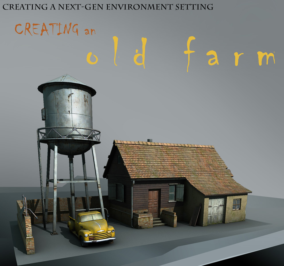
Creating an Old Farm
This tutorial is targeted at those with an intermediate level of modeling and texturing experience and it’s meant to be a „making of”. Not being a step by step tutorial, this will resume itself to presenting the pipeline typically employed at AMC Studio when creating a building or another type of next gen game asset. Even this pipeline is not a fixed one, but depends on the specific requirements of each individual project so this tutorial details an „average” pipeline composed of all the techniques our team used in the past.
I took as an inspiration the typical American farm house but the model has some European influences added to enhance the personality of the building and the surrounding objects. Even if the scene as a whole is meant to be photorealistic, some of the details, such as proportions, colors, object placement or volumes are e bit exaggerated to make the game look more spectacular. This of course depends of the type of game in which the asset will be included, as the location of the player will be very important. The level of details is dictated by how far the player will be from the object and how often / how much will the player look at it. These requirements usually translate into polygon and texture budgets. More details as the tutorial progresses.
On the software side, the programs used are Maya and Photoshop.
The pipeline can be split into five stages as follows:
1. Gathering materials and references
2. Concept art
3. Modeling and UVs
4. Texture layout and UV
5. Mapping
1. Gathering materials and references
In this first stage I gathered reference photos of the objects that will make the farm, being careful to choose them from the same time period and making sure they all have the same stile to make sure they all fit in well with each other. For this project I’ll make a house, a small water tower and a pickup truck. Usually, objects like the pickup and water tower are called props.

The colors and details will probably be changed later so that the elements match better.
2. Concept art
Using the reference photos I drew some quick sketches of the details that have to be included in the scene. I added some extra one that might be eliminated later due to technical limitations.

These sketches will serve as a basis for a more detailed concept that will also contain information about colors, materials, and reflectivity as well as clearer volumetric and architectural details. More detailed sketches can be obtained by using programs like SketchUp, but for the purposes of this tutorial, hand sketches were used as reference for the general object placement and proportions.

3. Modeling and UVs
Using one of the concept images, I’ve measured the dimensions of the building, modeled the big volumes. Further details have to be added in step by step.

At the same time I have to be careful not to model details that are either too small or need too many polygons. Most of these can be added in with textures. Depending on the game’s engine there’s a balance between what can be done with geometry and what can be done with textures. To make sure the result is optimal, it’s ideal that the same person does the geometry and texture. In the games industry, optimizing the execution time is very important for all the stages of building an asset. For modeling all useless polygons like the ones that are not visible have to be removed. The vast majority of the mesh has to be built using quads; the use of triangles must be limited to areas where quads cannot be used.
Here are some typical details that can be added via polygons:

This next image shows how I created and optimized the roof and one of the windows using the extrude tool.

Here’s another example of optimizing geometry, this time some planks that are leaned against the wall and a segment of the brick wall. Some of the details have been added later on in the creation process, after the textures have been created. These details include the missing bricks in the wall and the shape of the wooden planks.

These last two examples are here to accentuate the fact that the geometry can be also optimized after the mapping phase. For example, if we would have added the missing brick detail before doing the textures, the textures would have been harder to build „around” the geometry than vice-versa. As you can see, the geometry is very low in polygons, because small details like bricks, planks and roof tiles can be added in the texturing phase by means of normal maps. So in this case, only the large volumes will be represented by geometry, as the polygon budget for the building is just 1300 triangles. The water tower will have approximately 1000 triangles as its round shape requires more polygons. Going up in complexity, the car will have 2500 polygons. Being a prop asset, the car cannot be driven by the player so there is no interior
for it and the car does not have a complex setup, like allowing the doors to be opened.
Usually a prop car can serve as a cover for the player and the water tower can be used as a viewing/firing station. These are details that have to be taken into account when modeling for games, as some objects have
to be usable and certain places have to be in the reach of the player so enough room must be provided for him/her to pass trough them without getting stuck. As next-gen games mean that the player go almost anywhere and see most of the asset from up close, the texture resolution (measured in pixels/meter) has to be consistent throughout the asset. Special care has to be given to neighboring pieces, as their texture resolution has to be exactly the same.
From the beginning of modeling, we have to keep some the model under the final polygon limit, as some details might have to be added later, or more cuts have to be done in the geometry to aid mapping the object.
One of the frequent problems faced by game artists is whether to build the asset under the polygon limit and then add more details if needed or build the geometry in higher resolution and then reduce the excess polygons to meet the budget. This is a personal decision that differs from artist to artist based on his own work style. When modeling for games in general, the silhouette is the second most important thing after the proportions of the building. A complex silhouette „fools” the eye into thinking the object has higher resolution than it actually has.
As mentioned earlier, we’ll add details to the contour of the building, things like missing roof tiles, wooden pieces, broken corners, extruded or missing bricks, deformed signs, and broken steps in the stairs, etc. These types of details make the building look more natural, so they have to be placed in easy accessible places by the player.
Before unwrapping the UVs, we have to make sure that the geometry is clean and that the scene is nice and organized. The scene can be organized by naming objects and placing them on layers. Also, using the Outliner in Maya we can delete any extra nodes that are not used in our scene.
Using Cleanup we can make sure there are no errors in the geometry. The geometry is clean if after applying the cleanup command using the following settings, we do not end up with any selected geometry elements.
After this has been done, the scene can be further optimized by using File->Optimize scene size and Edit- >Delete all by type->History. To make sure all the polygons have correct normals, you can use Backface Culling to see if the normal orientation is ok or not.

Moving on, here are some of the most common modeling mistakes:

After modeling is complete we can finally move on to unwrapping the UVs. This stage will not result in a final layout for the UVs, in stead we’ll focus on creating correct UVs for all the polygons. For example, if the project requires 128 pixels per meter, than a 4m x 4m area will require a 512×512 texture and a 2m x 4m area will require 256 x 512 pixels. The brick wall in our scene has a height of 2 meters, so it will require 256 pixels for its height and some extra ones for the thickness. Being a long wall, we’ll have to us a lot of texture space if we are to keep the resolution rule and to avoid tiling the texture too much.
After modeling is complete we can finally move on to unwrapping the UVs. This stage will not result in a final layout for the UVs, in stead we’ll focus on creating correct UVs for all the polygons. For example, if the project requires 128 pixels per meter, than a 4m x 4m area will require a 512×512 texture and a 2m x 4m area will require 256 x 512 pixels. The brick wall in our scene has a height of 2 meters, so it will require 256 pixels for its height and some extra ones for the thickness. Being a long wall, we’ll have to us a lot of texture space if we are to keep the resolution rule and to avoid tiling the texture too much.

4. Layout, texturing and UV
Even though we refer to it as „UV layout”, the layout in fact refers to the way the details are arranged on the canvas in Photoshop. The easiest thing to do is draw a „layout” on a piece of paper to try and find the best possible way to arrange the different area by using the smallest texture size possible. Having correct measurements of the geometry is critical to ensuring the proportions of each area on the texture are correct.
So, the larger the area on the geometry is, the larger the allocated texture space has to be. For our asset, the predominant details are the brick wall, the plank wall, the roof and the wall of the shed. Details like the doors, windows and stairs will also be included here.
As you can see, buildings and props do not use a dedicated UV space with fixed texture sizes like characters or vehicles. So the UV process is actually composed of three stages:
1. unwrapping the UVs (done after the modeling phase)
2. texture layout (done in Photoshop/on paper)
3. mapping (done in Maya). This is done after the textures are done, when the UVs are positioned to use the created textures.
Texture tiling is used to minimize the number of textures. Some textures tile horizontally, some vertically and some of them even have tiles inside them. Here are some tiling examples.

On the left, there is a blue wall texture that has the dirt on the top and bottom areas. To maximize its use, the texture is has can be tiled on the vertical axis, the area in the middle can be tiled horizontal (the red arrow shows the area’s extremities). Using this layout, a tall wall can be textured using this single texture while keeping the extremities „dirty”. The image on the right shows a few example of horizontal tile (bottom area) as well as some circular tiles. All these internal tiling textures have to be matched by corresponding geometry.
Here are two objects mapped using these textures.

Going back to our main scene, I’ve tried to optimize the number and size of the textures as much as possible while at the same time keeping enough extra textures to add specific details to some areas.
The hand drawn layout for this scene looks like this:

The first part is the layout for the main texture for the house, which will be a 1024×1024 in size. This will contain the long brick wall, the wooden wall as well as the building details like doors, windows, stairs, etc. The roof tile will use a separate 512×1024 texture. On the bottom left of the image is the layout for the 512×512 water tower texture. The 256×256 alpha texture on the right will be used for the girders and the ladder. This texture will help us save a lot of polygons that would have been used for this type of details. Apart from the textures, there’s also one 1024×512 for the pickup truck.
As you can see, the sketch doesn’t have to be too precise, it just needs to help the artist better position the elements on the canvas, so there is little to no space unused. In case there is some extra room on the texture, some elements that need fine detail can have their UV’s scaled up to have better resolution. This should be done with care as differences in texture resolution can be quite obvious is exaggerated. There’s also a fine grid I’ve drawn there for each 128 pixels, to make things easier.
Here is the finished main diffuse (color) texture.

Diffuse map
Because this is a photorealistic building, the textures have to be carefully chosen. They have to have good detail; they shouldn’t be blurry or contain artifacts. The most important thing to look for is interesting details for the material needed, as the color can be easily changed in Photoshop.
Some details look better if they are exaggerated a bit, even in photorealistic textures, to add extra character to the object/building. The building has to integrate well into the game through chromatic, style, age, etc. The source photos have to be modified as little as possible as not to end up with a boring over filtered monochromatic image. So the texture has to be realistic and believable to compensate the lack of geometry.
Separate details have to be distinct and well placed on the texture to avoid obvious tiles and to make it easier to read.
One thing to be avoided as much as possible in Photoshop are layer blending modes. Normal should be used as much as possible, although Overlay, Color Burn or any other blending mode can be used if it doesn’t affect the final look.
Layers are another element that should not be overused. Using to many of them makes the work hard to manage, especially if they are not named and grouped properly. The best thing to do is to keep as few layers as possible keeping only the layers that control specific characteristic of the texture, like color, volumetric details. Some of these layers will also help to generate the rest of the textures, like normal and specular maps more easily.
As an example, these are the layers that make up the wall texture:

Height map
To create a more efficient normal map, we first need to create what is called a height map. The creation process is similar to creating a bump map which is then transformed into a normal map by using the nVidia Photshop Plugins. The normal map process needs to start with a careful examination of the diffuse texture because it might be tempting to just desaturated the image and run the nVidia filter on it, but that will have the desired effect. The height map has to be done in layer starting with the large volumes by using gray values to define the details. The next step will be transforming smaller details into height map. This step by step approach will ensure the best quality for the resulting texture.

Starting from the left of the image above, you can see increasingly finer details being added tot the height map. The image on the right shows the fine details that have been converted into a separate height map layer. Each height map layer can be converted to a normal map and then the layer blending mode will be set to overlay. Layers that need to be more accentuated can be duplicated so the effect of the overlay blending mode will be more pronounced. The intensity of each layer can also be turned down by decreasing the layer’s opacity. Make sure the details are defined using the largest grayscale range possible. This will increase the details’ fidelity on the resulting normal map.
The height map generation process is very important as a proper set of height map layers will result in less work being put in the normal map layers resulted.
Normal map
The image below shows the step by step process of improving the normal map after it has been generated. Some areas had been accentuated by duplicating the area on a new layer and changing the blending mode to overlay. This results in sharper, deeper details that cannot be obtain directly by converting using the filter.

Better conversion results can be obtained by using CrazyBump as it uses algorithms to compute the depth of the texture when generating a normal map. It can also detect details based on their size and treat them accordingly. Usually, CrazyBump is better used on large details in the textures. Another use for it is that it can extract information out of pictures that have directional lightning. The results include occlusion maps, height maps, bump maps, etc. These can also be useful to further enhance the textures.
Here is one area of the building with the normal map applied:

Also, these are the settings used for the nVidia Normal Map Filter used in this tutorial:

Specular map
The specular map’s basic role is to dictate how much light is reflected of a surface. Materials like wood, brick or concrete will have lower specular values while glass, metals and other metals have higher values. As with generating the normal map, the specular map requires careful examination of the surfaces involved to guarantee proper results. Some 3d engines use a grayscale specular map, some use a colored one. The image shown below contains a portion of the final specular map. The bright areas represent the windows with some dark areas for the parts that are dirty. Next, the metal surfaces have brighter values with dark areas for rust and brighter areas for shiny details like the door handle, hinges and rivets. The darkest values
are for the bricks, concrete and wood. Of course, if the wood is painted, its specular value will be higher, same goes for wet bricks or polished ones. Another rule would be that older surfaces tend to reflect less light than new surfaces as they are affected by dirt, dust and/or rust, all of which have very low specular values. In general, the specular map will have more contrast than the diffuse color it has been generated from.

The texturing process requires that the artist checks the asset constantly in the 3d viewport after each texture save. It’s also a good idea to adjust the texture intensity and color when all textures are done to ensure that they match each other. One of the reasons is that the lightning of the asset will change dramatically after the normal map and specular map are added.
5. Mapping
Mapping involves arranging the initial UVs to conform to the layout created at the previous step so that no areas on the texture are left unused. Also, UV mirroring should be avoided as it leads to „butterfly” artifacts.
Also, the scaling of the UVs has to be kept proportional to avoid obvious differences in resolution. The effects of such problems can be observed in the following image:

The next image shows the main texture with the UVs mapped on it. As you can see, all areas are used.

After the entire building is mapped, there is still room for adding some details like crooked or broken off roof tiles, missing wooden planks or bricks, a broken staircase, etc. This is done now as it’s easier to cut the geometry using the texture details than vice-versa.

The water tower has been done using the same methods. I tried reusing the texture as much as possible to increase the resolution. The same texture area has been used for the roof and bottom of the reservoir. The lower tileable area of the texture is for the pillars of the tower as well as the ladder and handrails. Besides this texture, I’ve used the 256×256 alpha texture for the framework.

All in all, technique differs from building to building, but the pipeline does not change much. The one vital aspect is optimization, being it geometry, UVs or texture. This has to be done as much as possible without compromising the shape of the object.
Moving on, the truck will require a slightly different approach, because vehicles can’t be done with tiles. That means that after the modeling is done, the UVs have to be done and then mapped before starting work on the texture.

The top part of the previous image shows the initial pristine model of the truck. The bottom images show the desired abandoned model that will be used in our scene. The advantage of building a pristine version of the object first is that we’ll have two separate models that can be used in the game.
This next image shows the finished UVs, unwrapped, scaled to proportion an organized to maximize texture space use.

Creating the UVs for such a vehicle requires a careful analysis of the reference photos to decide which areas will have dedicated UV space and which can be mirrored or overlapped without causing artifacts. Reference photos should be checked carefully for any details that might be added to the texture. The layout presented above has most of the elements mirror mapped but for unique details like the bumpers, radiator grid and cabin; the UVs have been kept unique. Here’s a more detailed image of the areas that have mirrored UVs:

The red areas with the same number have identical UVs. The sides of the car can almost always be mirrored as they are not visible in any one view at the same time. Areas that have been mirrored and require attention when texturing are the hood and the truck bed. The „butterfly” artifacts can be avoided in mirrored areas by adding a smaller amount of contrasting details on the texture.
Using the above UVs, here is the final truck diffuse texture:

As you can see, the hood area lacks rust and other particularities to make the mirror less obvious. Also, the rear bed area has details that don’t have too much contrast in it to serve the same purpose as the hood texture area.
Also noticeable is the lack of illumination in the texture. The engine will be creating the lightning and shading based on the geometry and normal map. Details like the scratches will look a lot better with corresponding normal map detail.
Adding shadows on the diffuse map will usually interfere with the engine’s details, giving the object an unrealistic look so it is to be avoided.
In the next image, you can see the final normal map generated using the same methods as the one done for the house. The dents in the metalwork have been generated in Crazybump to give it a more organic look.

And finally a render of the final scene:

Closing words
Now that we have reached the end of the tutorial, looking back, the process might seam lengthy and complex, but in reality, the pipeline is the same for most objects and only changes slightly depending on the project and type of asset. The main focus of the artist is to put character into his creation, no matter how visible or not the asset is in the game. Each object has to have details that are meant to attract the view of the player, which could potentially make him stop just to admire the scene. But this is not all, as the object has to be free of errors and artifacts and be optimized and up to the technical standards required by the engine. Next gen hardware may support a lot of polygons and textures, but optimization still plays and
important part of the creation process.
I hope this has been a useful tutorial for you and that this will help you understand better how some objects in your favorite game might have been created and what is expected from a 3d artist which wants to start working in the gaming industry.


About The Author
You might be interested in