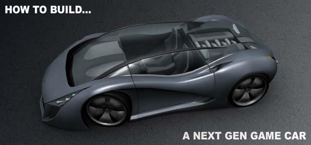
Tutorial “Next Gen Vechicle Creation”
This tutorial is intended to present a method of creating a next gen vehicle asset. The difficulty level is medium, so to better understand and use this tutorial, the reader needs to have a basic understanding of the processes involved in modeling and texturing an object in Maya. The asset presented here will be a generic vehicle with a low polycount that has diffuse, specular and normal map textures.
The descriptions will therefore be general but I will go into detail to explain the particularities of next gen asset creation every time it is needed.
Generalities:
To make the work easier, this tutorial is split into five different parts:
I. High-res modeling
II. Low-res modeling
III. UV layout
IV. Texture baking
V. Texture creation
One important thing I have to mention beforehand is that saving the scene as often as possible is a very good idea, especially when working on a complex asset such as this one.
Maya’s incremental save feature is good, but saving one new scene for each major step of
creation will ensure plenty of back-up scenes to go back to in case you need to.
The concept:
Often, modeling a vehicle is easier when official blueprints are available, but there are
situations when these are not available, so the modeling process has to rely entirely on
reference photographs. There are also cases when the entire documentation of a vehicle is reduced to a concept sketch. This is the case for this tutorial as the only reference I have is this perspective drawing of a concept car I drew. To make things easier, I also sketched a simple side view to help me get a better idea of the proportions of the vehicle. I will modify some of the shapes of the vehicle as I model it to improve its shape, as it is usually acceptable to do some modifications to the initial concept.


I. High-res model
The first step of the process is also the most important as the high-res model defines the general shape and proportions of the vehicle and will have a major impact on the entire asset creation pipeline. Usually, modeling the entire car in high-res is not required, but for this tutorial I will model everything that is visible in the final model.
A good starting point is the wheel placement. The resulting „frame” will give you a good
starting point for defining the car’s proportions.

Even thought the car is not even started, the wheels will help define the car’s front and rear width and wheelbase as well as wheel dimensions.
I start by placing a single polygon at the right-front corner of the car and matching it to the side drawing. Then I extrude another polygon from one of its edges. After each extrusion, I check the newly created vertices and move them in both the side and perspective view to make sure they are in the right place. This procedure can be extended to the entire car, but I only use it for the general shape. For the details I usually use polygon primitives as base. There is another way to build the mesh by using the so called “box-modeling”, but my personal experience has taught me that the multiple extrusion method is a bit faster and easier to grasp.

Continuing the side of the car, I will add the details by cutting the geometry using the Split Polygon Tool. I try to keep the polygons evenly spaced to make the mesh as optimal as possible.

After defining the cut in the side view, I move to the perspective view to adjust the vertices.

After that I return to the side view and do some more adjusting.

It is vital that the artist checks the polygons he just created as often as possible and from as many angles as possible. Checking will probably take more time for each new part/polygon than actually creating it, but this is necessary to ensure the quality of the work.
By extruding, cutting and moving vertices around, this is how the side looks like:

The basic shape can be obtained by extruding the border edges of this geometry. Notice I
haven’t extruded the bottom part as it is not necessary to have that area high-res.

Next is the front air intake, the smaller front side intakes and the basic shape of the
headlight:


I then cut the shape of the glass roof from the main body geometry. I will use the extracted faces as a base for the roof. To get a better view of the entire car I duplicate the side as an instance and scale it by -1 on the x axis.


For the security arch of the glass roof, make a copy of the glass roof and then cut a shape using the Split Polygon Tool, which will then be extruded to get the desired shape.

Lattice. I used these settings but the different parameters can be changed to better suit
each vehicle:


As the basic shape of the car is ready, I will save a separate scene with this geometry to later
use as a base for the low-res model.
With the final shaped improved, I can then move to modeling the medium size details like
intakes and outlets. here is for example how I added one of the frontal intakes:

As you may already know, the modeling process should be done by using 4-sided polygons,
generally called quads, to avoid any artifacts when applying Smooth on the mesh. Triangles
are to be avoided; in turn it is preferable to use polygons with more than 4 sides if
absolutely necessary. Usually a 5 sided polygon doesn’t affect the smoothed shape too
much, but checking if it does affect the mesh will determine if it is ok to use it or not. Here is
an example of such a case (the selected polygons are five sided). The second image shows
that area with one level of smooth applied. As you can see, the five sided polygons do not
affect the topology too much so they are acceptable in this situation.


The wheel
The wheel will use a polygon cylinder primitive as a base. This cylinder will have about 4
times as many divisions as the number of the spokes the wheel has. My wheel has 5 spokes
so the cylinder will have 20 divisions.
I only keep a „slice” of this cylinder and instantiate it to reconstruct the wheel. This way I
can work on one segment and visualize the entire wheel at the same time.


To make the wheel look more realistic I separate the tire from the rim. Adding a “lip” to the
rim will also help differentiate the two pieces.


Being a sports car, the rear wheel will have a “deep-dish”, accomplished by simply moving
the center of the rim inwards. Small details like this go a long way to make the car look
believable.

There is no interior modeled for the high-res wheel as this area will be barely visible on the
final car and therefore will not require any special details on the normal map. This is often
the case with high-res models that are going to be used only for baking maps as there are
some areas that need not be modeled because they will not influence the final low-res
model.
Body details
One thing to be careful about are the geometry intersections. These are to be avoided
because they tend to cause problems. To minimize problems, some of the topology might
have to be rearranged to make the separate pieces match at a vertex level. This way, the
smoothed meshes will intersect without causing rendering problems.


Before applying smooth, some of the edges of the model have to be “strengthened” by
adding some parallel cuts to them. This can be done by using either the Split Polygon Tool or
Select Ring and Split Edge Ring.


For the wheel cut-out, a small extrusion will make the area more believable as most cars
have this detail.


The same detail, applied to the rear wheel:

One thing to be aware of is that for the seams between parts to look good, the topologies
have to be similar and the meshes should have matching vertices on the borders. This will
ensure the objects will have identical borders even when smoothed.


Going further into detail, the headlight can be modeled from separate pieces to keep the
process simple. The interior and glass have both been constructed from the geometry
already done for the exterior of the car. The only scratch made parts are the cylinders
inside.


The brake disk is one element that doesn’t require too much detail as it will not be too
visible on the final model. Modeling the big details is enough as smaller ones like slots,
holes, grids, rivets can be done with textures. To further optimize it, I only modeled the
details that face the exterior of the wheel, leaving the interior face flat.

The interior
The best way to start the interior is to use the exterior as a base. By extruding the borders of
the exterior inwards, the interior can be created very easily. The next couple of pages
contain some screenshots describing the way the interior was built. There are not many
descriptions as most of the images are pretty easy to follow.
The engine bay:


The cockpit and door:

For the door I used two already modeled pieces of geometry as base:
-the door thickness is made using a part of the cockpit. (selected in the image)
-the exterior of the door was already created when I did the exterior of the car, I just
have to combine it with the thickness;
-the interior of the door is the only part that has to be scratch built.

The steering wheel
The base is a simple torus primitive. The interior is made from a simple plane modeled to
the desired shape and then extruded.


The seat

And finally, some screenshots of the finished interior:


As you can see, the level of detail in basic, as the interior will not need too much normal
map detail apart from the general shape. Adding small details is done in a much faster way
by using textures.
Next chapter will deal with the ingame geometry and the challenges of keeping the model
as low on polygons as possible.
II. Low-res model
At first sight, the processing power of a next gen console might seem enough to render huge
amounts of polygons and allow the high-res model just created to be rendered in full detail
in real-time. The problem is that a vehicle is just a part of the scene rendered by the game
engine. 20.000 polygons might seem low, but if you consider that some racing games can
have many cars on screen at the same time, that adds up to a lot of polygons being
rendered. That is why games require different models with different detail levels to be
created for each vehicle.
The first mesh used is usually called „ingame” and it is the model players see in the actual
game. This one has around 10.000 polygons for racing games and much less than that for
games that contain more complex scenes, like Grand Theft Auto type of games. This model
is optimized to be viewed from a medium distance so certain parts of the car have little to
no detail to save on polygons. The underside is usually flat, there are no suspension parts
unless the car is an open-wheeler and the interior has less geometry detail than the
exterior. The geometry I will build for this tutorial’s subject car is pretty simple as shape
goes so I will set the polycount limit to about 7000 polygons, including wheels and interior.
For the low-resolution model, the modeling rules are stricter that in the case of the low-res
model because the optimization of the mesh plays a more important role. Realtime
rendering is done using triangles, the only geometrical shape that a video card can
“understand”. All other more complex 3d shapes are converted to triangles when rendered
or exported to a game’s rendering engine. This automatic conversion can cause problem if
the source polygon has more than 4 sides, because it might tessellate in an
incorrect/inefficient mode. This is why only quads are to be used. There are areas where
quads probably won’t do, so triangles can be used to fill in these areas.
As mentioned at the beginning of this tutorial, saving a different scene with basic high-res
mode of the exterior is used as a base for the low-res model. Still, it seems I forgot to save a
good intermediary mesh for the wheel so I will have to build it by using the full detailed
mesh. This might also be the case in some situations, when the artist is required to build a
low-res model using an already finished high-resolution mesh.
First thing is to eliminate all the close parallel cuts in the geometry that were used to
strengthen the high-res model. A simple way to do this is to use Edit Mesh->Merge Vertices
on the entire wheel mesh. The Distance value can be tweaked to make sure that only the
very close vertices are merged.


Next step is to reduce the unnecessary polygons by deleting the edges that do not influence
the shape too much.

The high-res wheel didn’t have an interior, but the low-res still requires one that will be
visible in the game. As the car has a very small ground clearance, the back of the wheel will
be barely visible, so just basic geometry there is enough.

Setting up the normals in Maya
The way the object is illuminated is defined by normals, which are a vectorial attribute
assigned to each vertex. This vector defines the direction in which the light is reflected off
that vertex. To make it easier to setup vertex normals without having to define them one by
one, Maya uses an attribute applied to each edge called Hard Edge(Normals->Harden Edge)
or Soft Edge (Normals->Soften Edge). In short, if one edge is „hard”, the geometry will look
like it is broken on that edge. Contrary, if the edge is „soft”, the mesh will have a continuous
aspect on that edge. This is done by splitting one vertex into a couple of vertices with
different normals for each one to create the „broken” appearance of the geometry. The
lightning for a soft-edged area is calculated by averaging the values of the normals of
adjacent vertices.
Modeling for games will almost always mean that the normals have to be adjusted for the
model to look its best. The problem comes when there is a normal map involved, normal
map that requires as few hard edges as possible. I will talk more about this necessity in the
4th chapter.
First thing to do before setting up the normals is using the Normals->Unlock Normals option
to unlock the normals and allow for proper editing.
The starting point is the mesh with all of its edges set to soft. This is done because there will
be less hard edges than soft edges, so it makes sense to set them all as soft and then just
change a few to hard as necessary.

As you can see, the wheel doesn’t look that good with all the edges set to soft. The strange
shadows visible on the mesh will have an adverse effect on the quality of final lightning with
normal maps. Here are some simple rules that I use when setting up normals:
a.
All border edges count as hard edges. (not a rule, but a fact to be remembered ).
b.
For curved continuous surfaces, set the edges as soft (2 and 3 in the image)
c.
For angles that have a concave shape, use hard edge (4)
d.
For angles that are close to 90o use either soft edge if the edge is facing the
camera (5) or hard edge if it is not visible(6)
The last rule is good for objects that do not rotate in the scene. As always, these rules can
be broken as long as the final result is good.

Using the above rules, here is how the wheel looks. The continuous edges are hard and the
dotted line ones are soft. This view mode can be activated by shift right-clicking on the
object and selecting Soften/Harden Edge->Toggle Soft Edge Display.

I recommend setting up the normals before optimizing the geometry. This way you can take
shading into account when the polygon reduction is done. As the hard/soft edge setting in
reversible, it is easier to change edges from hard to soft or vice-versa than to reduce the
entire mesh with all the edges set to hard only to realize that once the normals are set,
some areas require extra polygons.
Next, some images that show the way the normals are set on the car’s body:


If the high-res geometry had intersections, it is preferable that the ingame version has none.
Partially occluded polygons will most likely lead to artifacts in the game’s engine. Topology
has to be redone in certain areas, and fully occluded faces can be deleted to avoid rendering
artifacts.

Now comes the polygon reduction part. In the following images are basic descriptions of the
most common polygon reduction methods and some areas where they can be applied.
1. Select Edge Ring and Collapse

2. Select Edge Loop and Delete Edge

The borders of the low-res model are very important. They have to match the high-res
geometry very closely so that baking the textures will not result in “blank spots” on the
normal maps because of improper overlap. The white wireframe object in the next image is
the high-res model without smooth. The green wireframe object is the low-res. As you can
see, the two shapes might not be identical, but the borders are very close to each other.

Moving on to the wheel wells, the quickest way to make them is to select the border of the
wheel well and to extrude it in.

After filling in the wheel wells, the rest of the underside can be constructed using as few
polygons as possible.

Speeding up things a bit, here are some of the other parts reduced to low-res:


The final low-res model will look like this. Note that each different color represents a
different material that will ultimately have a different texture. The final polycount is 7116,
just a bit over the initial estimate.


The next chapter of this tutorial contains details about the UV creation process.
III. UV Layout
The vehicle in this tutorial will have the following textures:
Window: 256×256 with alpha
Interior: 512×512
Wheel: 512×512
Exterior: 1024×1024
The entire UV process will be done using a checkered texture applied to the object as a color
map. This is done to make sure all the UVs are proportional to each other and if each
individual UV shell is aligned properly and make sure there are no distortions.
The main tool used for making organic UVs in Maya is Polygon->Unfold. Here are the basics
on working with Unfold in four easy steps:
1.
Start off by applying a simple UV modifier on the entire geometry, something quick
and simple like CreateUVs->Planar Mapping. Settings are not important, the goal
being to obtain only one UV shell for each geometry piece.
2.
Using Polygon->Cut UV Edges (in the UV Texture Editor menu) cut the UV shell into
more shells to avoid UV overlapping.
3.
Apply Unfold to each UV shell one by one. The basic settings can be observed in the
next image. Note that I ticked the „rescale” option to make sure the UVs will have
the same scale. The results should cause as little distortion as possible when the
object is viewed in 3d with the checkered applied.

4.
Each UV shell has an attribute called winding order. This defines the order in which
the UVs are displayed, either in a clock-wise or counter-clock-wise manner. To view
this attribute, use this button in the UV Editor:

Once the button is pressed, each shell will be colored different according to the winding
order. Some shells will be blue (normal winding order), some will be red (flipped UVs).
This display mode is additive, so overlapping UVs will have a more pronounced color,
making them easier to spot. As this winding order has a big impact on how the normal
map is generated, keeping all UV shells blue will help a lot when baking this map.
5.
After all the UVs shells are correct, the next step is to scale and arrange them in the
0-1 UV space. The way they are arranged has to be as compact as possible to
minimize the unused texture space. I start the compacting with the biggest shells
and arrange them starting from one corner of the 0-1 space.
The window UV
The following images contain one of the most common problems an artist faces when doing
UVs using Unfold and some methods of minimizing or eliminating this problem.
As I mentioned earlier, the first step is applying Planar Mapping on the geometry. If the
resulted UV doesn’t have the same symmetry axis as the mesh itself, there are chances the
unfolded UVs will look incorrect, like this:

One solution is to start the UV process by using a more suitable way to do the initial UV. By
applying Planar Mapping from the top view, the UV will have the same symmetry axis as the
geometry. After Unfold, the result will probably be better, like in the following images:

This type of error caused by Unfold can be corrected by cutting the UV shell along its
symmetry axis, applying Unfold to each resulting half and then recombining the two shells
by using Move and Sew.

The wheel UV
The easiest and most logical way to do the UVs for the tire thread is to use Cylindrical
Mapping. To save texture space, the thread UV was cut in half and overlapped. I could have
used the entire width of the 0-1 space to make the tire texture tileable, but in this case it is
more important to keep the sides of the tire and the thread at the same resolution so I
overlapped them instead. I did the same for the interior of the rim; only the UV is cut in four
pieces and overlapped as that area is not visible too much in the scene. Same goes for the
inner part of the brake disc which was overlapped with the exterior to save texture space.

Interior and exterior UVs
The next images show the way the interior (1st image) and exterior (2nd image) UVs are laid.
Some things are worth mentioning:
1.Most of the shells are overlapped to save texture space. Do this as often as possible,
especially for areas that do not contain asymmetrical details, such as text decals.
2.Some of the shells are not overlapped as they will require unique detail on the
texture. For example, the front of the vehicle is not mirrored to allow the addition of
a logo in the texture.
3.Parts that are less visible on the car, like the underside, use less space on the UV, as
they do not require too much detail on the texture.
4. Even thought the rear of the car will be the one most visible while playing the game,
the seam resulted from the mirroring of UVs is small.
5.I recommend that the UVs to be cut on hard edges, because any seams that will
appear there in the texture will be easier to hide because of the sharp transition in
lightning between the faces.


The next chapter deals with generating normal maps and ambient occlusion maps.
IV. Texture baking
The Normal Map
In games, the normal map is used to add details to low-poly geometry. The information can
be extracted from a high-resolution mesh and then applied to the ingame model to improve
its aspect. The major advantage of this technique is that it can vastly improve the look of a
low-res asset without having a big impact on rendering performance.
Here is how it all works.
As mentioned in the low-res portion of this tutorial, lightning of an object in a realtime 3d
environment is done by using normals, which are a vertex attribute. The major disadvantage
of this technique is that the shading quality is proportional with the number of polygons.
Building a next gen object is almost synonym with using normal maps. Instead of relying of
mathematical procedures to determine the way light is reflected off a surface, the „per
pixel” lightning method uses a normal map to define the normal’s direction in every point of
its geometry. The major advantage is that the normals can be calculated from a high-res
version of the asset. Each pixel in the normal map will define the normal of that point in 3d
space as follows: the three color channels R (red), G (green) and B (blue) will determine the
X (red), Y (green) and Z (blue) values of the normal. There are two types of normal maps
used in games:
a. Object (World) Space Normal Map. Can be easily identified by the fact that it
looks like a rainbow. Each color channel defines the absolute coordinates of
the normal in world space. This type of map is used for static, non-deformable
objects and it is usually avoided as it is hard to change in Photoshop after it is
generated.
b. Tangent Space Normal Map. Can be easily recognized by being predominantly
blue. Each pixel defines the deviation of the normal from the value calculated
with the „per vertex: method by using a local coordinate system (X, Y, Z will
instead be U, V, N). This is the most used type of normal maps in games as it is
easy to edit in Photoshop and it can be applied to deformable meshes.
Scene preparation:
A good idea is to save a new scene before starting to prepare the scene for baking. This will
ensure that all the settings used for baking are saved separately in this new scene and are
easy to go back to in case of anything needing a rebake.
All the meshes should be recombined by following these rules:
1.
The low-res geometry will be separated in such a way that every object has only one
material. For example, the door geometry will be separate from the door window,
even if in the final scene they will probably be merged together. Naming these
meshes should be done by using a simple to follow naming convention like this:
body_low, glass_low, interior_low.
2.
As mentioned before, intersections must be avoided by separating objects because
they can cause artifacts in the baked textures. For example, if the interior has
intersections, I will separate it into different objects that will intersect each other but
will not contain intersections themselves. Naming should be something like
interior_low 1, interior_low 2.
3.
The high-res geometry will be recombined in a similar way to the low-res geometry.
Each previously created low-res geometry should have a corresponding high-res
counterpart named something like: body_high, glass_high, interior_high, etc.
These naming rules will help speed up baking by making each high-res/low-res pair easier to
select.
Don’t forget to apply Smooth on the high-res meshes before baking!
Texture baking in Maya can be done by using the Transfer Maps utility found under
Lightning/Shading->Transfer Maps…
The „target meshes” section is for the low-res meshes and the „source meshes” section is
for the high-res versions. The settings in the next image are a good starting point for baking.
The settings that usually need tweaking are „Search envelope” and „Max search depth:”

For each pair of meshes, a normal map will be generated. If there is more than one normal
map for one particular material, these baked normal maps can be recombined in Photoshop
by using the Overlay blend mode.
The combined textures can be loaded on the bump channel of a Phong material. The „Use
as” drop box in the bump2d node has to be set to „Tangent Space Normals” for the normal
map to correctly be displayed when high quality rendering is enabled (Renderer->High
Quality Rendering in the viewport menu)

This is how the mesh looks with normal vertex based shading.

This is how the mesh looks with normal maps applied in High Quality Rendering.

The Ambient Occlusion Map
This is a bit easier to explain: basically, the ambient occlusion (AO) map contains the amount
of „visibility” stored for each pixel. The more occluded that point is in 3d space in relation to
its surroundings, the darker the pixel will be on the AO texture. I will not go into detail about
how this is calculated, I will stick to showing how it is generated and used. Because
occlusion is influenced by all the objects in the scene, this map does not require the low and
high-res models to be separated to minimize the number of intersections.
Texture generation is similar in steps to the generation of normal maps. The next image
presents some of the settings used. One thing to mention is that for the AO baking, the
„Max Search Depth” setting is ignored. This is replaced by „Occlusion Max Distance”, which
usually require a value larger than 50 to give proper results.
The value for „Occlusion rays” is directly proportional to the quality of the final texture and
the rendering time. For a test render, a value of 16 will be enough, but to obtain a smooth
texture, I use a much higher value, usually a power of 2 (64, 128). Be careful, high values in
this field will cause the rendering time to increase dramatically!
The resulting image is a grayscale that can be put on top of the painted color texture using
Multiply. This will add depth to the diffuse texture, making it look more realistic.

Usually ambient occlusion maps take more time to bake than normal maps, so some
patience is required. Do a lot of test renders with low “Occlusion Rays” values to make sure
all the details show up on the map before doing a full resolution render that can even take
more than half an hour to complete. Now that these textures have been baked, you are
ready to move on to the next and final chapter of this tutorial, texturing.
V. Texturing
The Diffuse Map
The last part of this tutorial will present a simple way to create the textures for this vehicle. I
will use as an example the exterior texture of this asset to show an easy and effective way to
create textures in layers.
One important thing that I always keep in mind when texturing is that a lot of times, the
texture has to be corrected or changed during the creation process. If I just paint all the
details on one layer in Photoshop, later a simple color change can be impossible to perform
without redoing most of the texture. That is why the texture should be done in layers, by
keeping similar types of details grouped together for easy editing.
The base is a layer set which contains one layer for each material/color on the texture.
Naming these layers in a comprehensive way is a good idea and will make things easier.

Next layer set up we have the big details in the texture. I used simple shapes and some layer
styles to draw the grills. The headlight lenses are taken from a photograph desaturated and
pasted as a layer set to Overlay.

After adding the big details, it is time to add some subtle material variation. As this vehicle is
new and clean, I only added one layer with a metallic texture set to overlay. To keep
everything subtle, the layer opacity was lowered. Also, there is a mask to hide the metallic
texture for areas that do not require it. Masking is a good method of hiding detail and it is
preferable to deleting as it can be reversed.

The texture still looks flat and lacks depth. To add some variation to the huge areas of blue
car paint, I added a new layer of a lighter color, and by using its mask, I blended it with the
original one like so:

The texture is getting better but it is not done yet. Adding further detail can be achieved by
using the ambient occlusion map baked earlier. Adding it on top of the color texture with
the layer set to Multiply will add a lot of detail to the texture, making it fit for use.
This is how the texture looks after adding the AO map.

The Specular Map
A specular map defines the intensity of the specular highlight, effectively describing how
reflective a texture is. Creating this texture is fairly simple and involves using the color
texture as a base and modifying it. This is yet another reason to keep the color texture in
layers.
Every type of material reflects light differently, so each area will have to be adjusted to
reflect this. Very shiny materials like glass or chrome will have a very light color on the
specular texture, usually white. On the other hand, matte materials will be defined by dark
colors on the specular map. Pure black is to be avoided as having an area without any
specular highlight will make it look very flat in the game’s engine because there will be no
highlight to show off the normal map detail. These are the two extremes; the rest of the
materials will have their specular color somewhere in between. There are no “standard”
values, so the artist has to create this texture by trial and error. Unless specified by design or
technical documents, the absolute value of the specular color is not as important as the
general contrast of the map. One trick used to enhance the look of metallic textures is to
change its specular to a color that complementary to the diffuse map. So here, a reddish
specular on a blue color texture will give a nice metallic effect. Another good idea is to
enhance the contrast of the small surface details on the specular map to make the specular
easier to read. This is the case of the next image, even thought the noise in the texture
might not be visible due to the screenshot’s resolution.

The Normal map
The normal map base is the texture generated in the last chapter. On top of this I will add
the details that have been added in the color texture. To extract a normal map from the
diffuse texture, there are two free programs that do the job well. The first one is nVidia
Normal Map Filter which is part of the nVidia Photoshop Plugins
(http://developer.nvidia.com/object/photoshop_dds_plugins.html). This plugin uses a
height map to generate the normal map. A height map is easy to create by using the color
texture as a base. Each pixel will have a grayscale value that represents its elevation. The
lighter it is, the more elevated/extruded it is. This value is a local one in the sense that each
pixel has its elevation defined in relation to its neighbors. A flat white height map will result
in a flat normal map as there is no variation in elevation. Basically, the process of converting
a diffuse texture to height map means desaturating the original layer and modifying it to
better reflect the elevation of that area.
This is the height map created for the exterior of the car:

Next are some hints about how to use the the Normal Map Filter in Photoshop. The settings
explained here refer to the next image.
1.
“Invert Y” is necessary so that the normal map will be correctly displayed in Maya
using the default settings.
2.
The recommended methods of generation are “Average RGB”or “Colorspace”.
3.
Experiment with the Scale value to obtain the desired depth for the resulting normal
map.

This filter has its limitations in the fact that the resulting normal map lacks depth, because
there is almost no information saved on the depth (blue) channel of the normal map.
When added depth is necessary or the source image is not a height map but a fully light
color texture, like a picture, the program to use is Crazy Bump
(http://www.crazybump.com/).
As an example, this is how the tire normal map was created. The base image is this one:

I used Crazy Bump 8.6 Beta which has separate buttons for opening height maps, pictures or
normal maps as sources. In this case I used “Open photograph from file”. Just as the Normal
Map Filter, this program requires some experimentation to better understand how it works.
To make it easier, these are the settings used to generate the tire texture:

The resulting normal map from these programs can be added on top of the normal maps
previously generated by using Overlay. More than that, Crazy Bump can also generate an
ambient occlusion map, so that can be used also to enhance the color texture. This isn’t the
case here as the source picture has enough detail to be added to the texture as is.
Finally, here are some screenshots of the final work done in Maya using High Quality
Rendering.


VI. Final words
I hope this tutorial was enjoyable to read and that the information in it is useful for you. The
pipeline described here is a very good indication of what is required for a 3d artist to
accomplish while working for a Next Gen game and hopefully this will help answer some of
the questions people ask when trying to find out more about how ingame cars are made.
Thank you!


About The Author
You might be interested in