Making of Varga by Paul Tosca

This tutorial is dedicated to 3DM3 community.
1.Intro
2.Game modeling workflows
3.Tools used
4.Workflow used for Varga
5.Final model
This is not a step by step tutorial. I will summarize the workflow i used for one of my characters with lots of images and some print-screens directly from the applications used ( maya/mudbox/photoshop etc …), also in the end i will provide some info about tangent space normal maps so you could think of this tutorial as mainly normal mapping related stuff.
Tip:whenever you see a hand cursor while hovering over an image you can click on it to see a high rez version of the image , like in the image below :)

This character is my entry for Dominance War II competition ( www.dominancewar.com ). The main theme of the competition was to design a game (low-poly) character and were some rules (limitations) about the specs we could use for geometry and textures( main character will not exceed 6000 triangles , 1000 more triangles for weapons/gear and we could use a pet also but the budget will come from main character; for textures we could use 1×2048 square for main character + pet, if any , and another 1×1024 square for weapons/detachable gear; diffuse, specular, normal,bump,opacity ,glow,reflection maps were allowed).
This tutorial is intended for game (low poly) characters and assumes that you have a basic knowledge of normal mapping and its use; you can search on google if you need more info about this subject ( a good start will be this page on zbrush.info ).
I will start by showing you the final files sent to the competition to give you an idea about the direction this tutorial is going.
concept sheet :

construction sheet :

texture sheet :

beauty shot :

winning pose :

Nowadays almost all games are using normal maps for ingame characters ,even mmos , so a high poly version of the character will most likely be needed to bake the normals for the low version. The normal maps can be done without the help of a high rez version of the model , from bump maps , even painted directly by hand ( i will show you some tricks i use to paint normal maps directly in photoshop later on ) though its less likely that you can achieve the same results as a high poly version will do.
The assets required for the creation of a character will most likely be:
- low poly version ( or multiple versions for different LODs)
- high rez poly version used to compute normals for the low poly one ( you could also bake occlusion maps and other maps that will help you later when texturing …see paragraph "4.3.Transfer maps" for this )
- all kind of textures that the game engine will support ( diffuse, normal , specular are the most used ones)
I suppose that a concept/drawing is available and the steps that will follow are modeling/texturing.
There are mainly two approaches you can take when modeling ( the difference between them being the order in which the assets are created )
- low poly model -> diffuse texture -> high poly model-> normal map and other textures
- high poly model-> low poly model -> normal map -> diffuse and other textures
Both ways can give good results if done properly and the choice will mainly depend on the pipe-line already established; i used to work both ways in the past but i prefer the last approach.
Though the low/diffuse/high workflow might have some advantages ( like the low poly version of the characters will be ready to go down the pipeline to animators earlier in the process ,or the creation of the highrez version will be quicker if you work carefully and keep lots of selections into the diffuse psd file than you can later on apply as displacemets on the high rez mesh) it has one big disadvantage and i will picture it in a quick example.
Let us say that below is a piece from a model (a shirt with some buttons)… i assume the low poly and the diffuse textures are ready …

The next step down the line will be detailing the low poly version so i will import a cleaned up version of the low poly into mudbox to upres and detail and i will also load the diffuse texture to check that the detail i will add will register correctly with the diffuse … then start to add divisions/levels to the geo and adding details like big folds and big volumes …

I will use height maps made from the diffuse texture to displace the fine details ( it will speed up the process and also this way i will make sure that the computed normal map will match closely the diffuse than if i will sculpt directly using the mapped diffuse on top of high ) …

All is working well and i will export the final level to compute the normal map with maya/3dsmax or other program that will use raytracing for the process and will assure proper display of the normal map in the final engine but if i was not too careful when detailing i will encounter something like in the images below ( the effect was exaggerated here so i can make a point )

You can see that the details in the diffuse on one hand and the normal map on the other will not register correctly … this is due to the fact that during sculpting of the big folds i displaced/shifted the geometry a little and though i used displacement maps to add details like buttons this will not assure that when raytracing the details for the normal map they will overlay perfectly with the diffuse ; to avoid this , the high rez detailing should be done with care if possible not big displacements from the original cage/low poly version … but this will hinder you since the whole point will be to add as much variation in the surface direction as you can and big volumes also.
The issue will be toned down if you will use zbrush and will compute the normal map not with raytracing but with zbrush internal algorithm that will take into account all the subdivision levels , but its less likely that the normal map will be displayed properly in other software / engine if you will compute it that way , the old problem of seam display : every software i used to compute normals (and i have tried a few) have a slightly different method of computing/displaying normal maps in tangent space.
The best way for this is to compute the normal map with the software that will assure no problems in the end , for this project i used maya for rendering and i had to compute the normal maps within maya to make sure they will render properly.If you are using normal maps computed within maya ( with transfer maps tool ) and want to render with mental ray renderer within maya than make sure to check that in the Render Settings dialog -> mental ray tab->Translation->Performance you have checked Maya Derivatives (like in the image below – note that this option is off by default) this way you will use Maya’s derivatives calculation for bump mapping providing compatibility with Maya for mental ray, also note that this option is only available when Export Polygon Derivatives is also on.

The second approach for modeling: high poly/low poly/uvs /textures will give you the freedom to start sculpting and adding details from the beginning and you will get rid of the problem stated above also.
However ,when modeling the high version first you have to keep in mind that this will be used to bake normals for a low poly cage and model it accordingly.
You will have to estimate what details worth adding and that could be used properly when computing the normal map for the low poly version.
For instance if i will have the high poly below

…i could use a single quad plane for the low poly but the result will not represent the high version very good when viewed from above they seem too look identical

but when viewed at slanted angle you can see that the single guad plane does poor in reproducing the high detail

a better approach is to spend a couple more polygons to make the low poly better match the high version

then the low poly with normal map will look better viewed at slanted angles ( of course ,depending on the polygon budged you could add more geometry to get rid of the rugged look )

Also,you have to avoid modeling complicated shape details that will be hard to enclose within a low poly cage later on because they will "eat" too many polygons to be displayed properly ,though you might be tempted to go crazy and add lots of detail like shown below.

The high res model might look nice but when building the low version on top of high you will always have to stay within a polygon budget (5-10k triangles or whatever) and if you did not plan high poly details in advance you might face the situation where you will need more polygons than alloted to better match the already high model , and you will have to go back and change the high version.But with some practice you will know what detail worth incorporating in the high version and what details to miss because will be hard to reproduce.
Another big advantage of the last workflow is that you could also bake an ambient occlusion map and other maps (a simple diffuse pass or even specular passes to give more variation to the textures) using the detail from the high poly model and you could use them as a starting point for the textures.
Also you could try a combination of the two methods shown above, in fact this is what i have done for Varga and i will show you later on in the following paragraphs.
Before i will start showing you the workflow i used for Varga i will summarize the tools i used for this project.
First let me summarize the specs of the pc i worked on because most of the limitations i encountered on the way were hardware dependent:
- athlon xp 2500+ @2400 ( but overclocking won’t do much good on this old machine :) )
- 1GB of RAM
- video GeForce 6600GT
You can probably guess that this is no high-end machine and i was way limited to the number of polygons i could use at the same time ( in mudbox i could go as high as 2mil triangles but it will move too slow ), in maya i had a lot of crashes when trying to import obj files bigger than 1.5 mil tris ( not enough ram) and i tried to break down the model into pieces (head, torso, hips, legs , arms etc) so i can achieve enough polygons to sculpt the details i wanted without crashes or unmanageable scenes ( usually the polycount per piece will not exceed 1mil tris ).
Regarding the software used ,I am mainly a maya user so lot of the work was done in maya ( modeling , uvs , texture baking , rendering ).
For high rez sculpting i used mudbox ( build a low cage inside maya and export it to mudbox for further detailing ).After the sculpting part is done i will export one of the higher level as an obj file ( usually a 100-300k tris mesh worked fine at this stage , no need to export the highes level ) and import it in topogun along with a low poly cage ( if i already have one , or build a new one from zero within topogun)and rebuild the topology to better match the details i have added to the high rez mesh.After this process was done i will import back into maya the low and high versions and compute the normal maps with transfer maps tool.
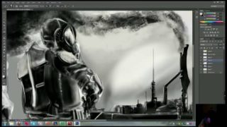
The normal maps were further tweaked within photoshop;some were done completely in photoshop ( check the maps for Peril- the bow later on ).
After all this chit-chat let me show you some wip images in the following paragraph.
Usually for game characters you will have some specs to follow : limit to the number of triangles , size and numbers of textures used; you will have to conform with the number/size of the textures but if you exceed the polycount by 500 – 1000tris ( lets say for 8k budget ) and the character is looking cool … it’s less likely the client will be mad :).
For this competition the limit was 6000 tris and i wouldn’t want to exceed that so the first step was to build a low poly cage to allot the polygons between all the assets (the main char , pet , weapon ) , it doesn’t have to be final but to let me see what details i can incorporate into the high version.
Below is a guick timelapse with the first low poly versions (the triangulated one is the final version though)

After i have modeled a low version of the whole character i had a better idea how to distribute the polygons between the main character the pet and weapon/gear. The next step is to start breaking the model into pieces and cleaning them up. For sculpting its better to have clean topology , mostly quad faces , try to aviod triangles and situations when more than 4 polygons will meet at one point( add extra tesselation to get rid of all the irregularities in the mesh … this way you will have more predictable results when subdividing and sculpting) , you can move triangles and points where more than 4 quads will connect in the areas that are less important/visible.Also you should aim for a topology that will have mostly square quads ( avoid polygons that are more than double in one direction than in the other …. add extra tesselations to fix this … remember this will be for high rez so the polycount won’t matter ).
Below are some pieces ready to be imported into mudbox and detailed further.

The next step is to import the cages into mudbox and add as much detail as you or your machine can … one will break eventually:).
This is the most fun part for me in the whole workflow …i will show you some time lapse images with the progress for some pieces.
boot (little below 1mil tris for the highest level)

hips (1.6 mil tris for the highest level)

leg (around 500k tris for the highest level)

arm (around 600k tris for the highest level)

torso (around 800k tris for the highest level)

below you can see the entire high rez model : 8.5mil triangles ( i managed to import all the pieces into maya for this tutorial on my new machine but maya will eat like 3.5G of RAM for this )

Now that the fun part is over i will take the low poly version i have done in the beginning and change it to conform better with the high rez version. I use topogun for this … import the low version and one of the higher levels as a reference model and i will change the topology however i want and i will make sure that the low poly will resemble as best as i can with the high version in order to get good normal maps when baking normals.

I will repeat the same process for every piece i have sculpted separately and when all are over i will be ready to go to the next stage : baking the normal maps.
At this point the low poly version and all the high rez pieces are ready and i will continue with the uv mapping.
There are a lot of tools for UVs that you can use :UVLayout, Unfold 3D, plugins for pelt mapping etc… and some say one is better than other but i do all my uvwork with the tools built within maya, they might require more attention and planning on where to cut the UVs and sometimes will produce junk UVs but after a second trial things work well. I have tried Headus UVlayout and Unfold also but i like better the maya unfold … works faster for me.
I won’t show you how i worked on uvs because lots of the people i know don’t use maya for uvmapping and most likely the information i will give will be redundant.
The idea is to unfold the uvs with little stretching ,a good hint is to keep your cuts in the less visible parts of the model(like for the arms and legs keep them on the inner part) and you could break down the uvshells accordingly to the pieces in the high rez version ( for instance boot will go as one shell , each leg as one shell etc … )
After the UVs are done i will be ready to bake normals and other maps if necessary.
I used transfer maps tool within maya for this ( but render to texture within 3dsmax works the same way ).
I will exemplify this process on the boot:
-before starting keep in mind that the uvs on the piece of geometry you are going to bake normals for should not overlap (in the end you can overlap uvs for arms or other similar objects but for accurate results move the overlapping uvs outside the 01 space or shrink them down in a corner or unused space while baking)
-import both low and high versions into maya and make sure they are on top of each other
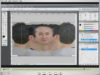
-open the transfer maps dialog ( found in Rendering menus in Lighting/Shading-> Transfer maps… )

-select the low poly version and in the Target Meshes click on add selected , then select the high version and in the Source Meshes click add selected (see image above)
( if you do not add any geometry to the Source Meshes then maya will sample all the geo in the scene for the process )
-in the Display option for the target mesh select Envelope ( or you can select both to display both the target mesh and the envelope)

-this will create an user-editable geometry ( merely an offset of the current low poly version ) that will be used as an envelope to look for the source meshes. You can change the offset of the envelope by changing
Search envelope% slider ( or by typing a value ); the idea is that you will get better results if you will have the high rez version inside the envelope (like in the third case in the next image)

if you go too far with the offset the baking might not work properly , usually i will trial and error some values for the offset until i have most of the high rez inside the envelope like in the image below

and then select the envelope and tweak its vertices/faces/edges until the high rez will be completely inside the envelope

-then select the maps you will like to bake ;i will resume to normal map ( you could also bake ambient occlusion maps … this way you will sample the ao from the high rez version but i did not have too much time to compute ao maps also because they require some time to render … depending on your machine … mine was too slow at that time for this ; instead i used Batch bake mental ray with the normal mapped low poly to bake a Final Gather pass for occlusion … works a lot faster with comparable results… see later on for details)
also make sure you browse for a path to save the file ,select file format,map dimensions and other details you want, also make sure you set the search method to inside envelope only since the high rez will be inside the envelope

-now you are ready to render to textures and hit the Bake button
-as a note make sure to save the file before you hit the bake button because after rendering the texture maya will delete the envelope and you might need it again ( especially if you spent some time tweaking it to better enclose the high rez ) or if your map does not look ok and need to rebake make sure to undo a couple o steps until the envelope pops up in the scene again ( saving the scene is safer though :) )
-if the normal map does not look ok from the first time come back again to the transfer maps dialog and readjust some settings ( but when you have an envelope that completely encloses the high its less likely problems will occur … you will have some hard time if the envelope intersects with the high rez … if you are too lazy to tweak the envelope you could set the searching method to "inside then outside" or to "closest to envelope" ; there are situations when it might work and situations when you will have problems : usually you will have problems when multiple surfaces intersects on the high rez version , lets say some straps on top of the arm … in those cases if the envelope intersects with the high geometry also then it might sample the wrong surface)
The same steps you have to follow if you are using Render to texture inside 3dsmax
-select low poly mesh go to rendering->render to texture
-check projection mapping ( to turn it on )
-push Pick and select the high rez model
-and next usually max will create a crazy envelope/cage ( autocreate process )
-select the projection modifier
-go to cage section and hit Reset to reset the cage ( the cage will fit the low poly exactly )
-in the push section you can change the Amount to offset the cage like in maya trying to enclose the high poly version
-same as in maya you can alter the cage by expanding the projection modifier and tweaking the individual elements until the whole high poly will be inside the cage
-after all the tweaking is done you select the low poly again and in Render to texture dialog you hit render
-if the map its not looking properly you might come back again and do more tweaking of the cage
Next,I will show you another cheap way of computing occlusion using mental ray and final gather on the normal mapped low poly version (it will not look the same as the ambient maps computed from the high version but will be a lot faster).
Lets say this is the final low poly with normal map (i will exemplify on the boot only but you can do the same for the entire character at once).

make a big plane and place it under your model

ake sure that the environment background color for perspective camera is white ( this way when final gather will be used and the rays will not intersect any geometry then the returned color will be wihte )

et the renderer to mental ray , make sure that you will check export maya derivatives
make sure in the Render Settings-> Common tab ->Render Options you will have the Enable Default Light option unchecked , its checked by default ( this will assure that maya will not create a default light and pass it to mental ray if you have none in the scene)and delete or hide all the lights in the scenes ( if any )

make sure to enable Final Gathering ( usually i set the Quality Preset in the mental ray tab to Production and then enable FG and increase the accuracy to 1000-1500 and leave the other options to default )

assign a new lambert to the low poly geo and set its color to full white and change the diffuse to 1
( also change the same options for the default lambert or assign a new lambert to the ground plane and set its color to full white and diffuse to 1 )

select the material assigned to the low poly geo and assign/connect the normal map texture into the bump channel
make sure you will use the bump as tangent space normals

before baking you can make a test render with mental ray and if all was done properly you should have a similar result

Next open the bake dialog found in the Rendering menu set under Lighting/Shading->Batch bake (mental ray) … go to the options and make sure you check bake shadows and orthogonal reflection, also set other options to pretty much what you see in the image below … set the file type and size and you are ready to go

Hit the convert button and if all is set properly you will end up with a texture like below (if you can not find the textures you could always check the log or if you did not enter a path in the dialog they usually are saved in the current project folder in renderData/mentalray/lightMaps)

It won’t be as crisp as an ambient map computed directly from the high version but will compute alot faster.
With the same process you can bake some quick specular passes to use for the textures:
save the same scene with another name( spec_bake or something ) and disable the FG in mental ray tab;delete the ground plane
change the material assigned to the low poly to blinn , change its color to black , specular color to white and reflectivity to 0

make a couple of directional lights and position them to light from above around the object

use the same batch bake mental ray options but it will compute super fast now ( its tracing only the specular pass) ( this time double the resolution when baking and you will donwsample it in photoshop to use on top of textures … you will achieve better results this way )
you should end up with a texture like below and you can overlay it on your diffuse textures with screen/color dodge blending modes ( to give more variations ) … it works great for plastic, metal, leather or other materials that have high specularity ( it wont look so good for cloth for example )

Enough said about baking … bare with me for the last paragraph ( i kept the cool tips for the end :) )
4.4.Further tweaking of normal maps in photoshop
This paragraph is for those of you who want to better understand normal maps and it may seem a little technical (it requires some basic knowledge of math , vectors and stuff like that ).
4.4.1.Some general info about TS (tangent space) normal maps
First, i would like to talk a little about normal maps , how they are computed/displayed.
I am more interested in tangent space normal maps ( world or object space normal maps are not suitable for characters or for objects that will deform ) so for now on when i will say normal map you will assume i am talking about tangent space unless stated otherwise.
If you are in the same situation i was when i first started with normal maps ( tangent space in particular ) probably the following info will help.
At the beginning i was really frustrated by the "Seam" problem :) : a normal map computed within a software will not display properly in another one , and i am talking here about the seam that will appear in the geometry where you will have an uv shell border.I have struggled to find out what the problem was … thought i am doing something wrong , read the help of each apps then started searching on the internet and after some research i finally got the idea about the problem , how and why it will occur …but not how to fix it though:)
The main problem resides in the way each application computes/displays tangent space normal maps.
Tangent space is represented by three vectors: normal ( that will always be perpendicular to the surface ) ,and two other vectors perpendicular to the normal called tangent and bi-normal ( or bi-tangent : i have seen that the names are used interchangeably though some say that the correct name will be bitangent since we are talking about a surface … for a curve in 3D , the tangent space we will have one tangent and two normals , normal and binormal …. for surfaces we will have one normal and two tangent vectors : tangent and bitangent but the naming does not matter much as long as we know what vectors we are talking about). These three vectors can be defined for each point on a surface and taken all together they define a coordinate frame.
Usually tangent space per triangle will be computed in the following way:
-the normal vector will always be perpendicular to the surface (triangle) (it will be the blue one and it will be stored in the blue channel of the normal map)
-the tangent(the red one stored in red channel) and binormal(the green one stored in green channel) vectors will be oriented in accordance with the UVs :tangent will be left to right(or right to left) in UV space (so it will be U coordinate in texture space ) and binormal will be down to up (or up-down) (so it will be the V coord in texture space) ;probably you have seen in many dialogs for normal maps the options to flip Red or Green channel , these options stand for the orientations of the tangent(left-right/right-left) and binormal (up-down/down-up) .. some apps use different orientation than others; you can flip the channels inside photoshop also, for instance to flip the Red channel you will press Ctrl+1 ( to go to the red channel ) and Ctrl+I (to invert it) then Ctrl+~ (control tilda , that will be left to 1 key -) to go back to full RGB image (same for green Ctrl+2,Ctrl+I,Ctrl+~).

Now lets say that i will cut the UVs along the edge and will rotate one shell 90 degrees CCW like in the image below.Because of the rotation in UV space the tangent space for the first triangle will be different than in the first situation ( the RGB triad for the first triangle has rotated also 90 degrees along blue axis )

Because of this , the orientation of the uv shells will affect the colors you will see in the normal map;if you rotate the uvs of your model ( or the uvs for some shells ) lets say 90 degrees ClockWise and recompute the normal map the colors in the new normal map will be completely different ( not because the entire image will be rotated by 90 degrees … you can rotate it 90 CCW in photoshop and compare it with the first version to check …. they will be different )
Tangent space per vertex will be then computed and after that you can compute the tangent space vectors for any arbitrary point on the surface by interpolating vertex tangent space vectors; usually more complex calculations are done so that the tangent space will be invariable regarding to tesselation (L shape problem) : for instance in previous versions of maya the computed normal map was dependent to tesselation … so if you would have a triangulated model and if you would select one triangle edge and flip it then the normal map would no longer be displayed properly due to recalculation of TS after flipping the edge … in the newer versions of maya this was solved ( usually special tools are used to prepare the geometry for per-pixel lighting by creating proper tangent basis at each vertex, NVMesh Mender is one of them)
Now ,for computing a normal map the raytracing algorithm will cast a ray from the current point of the low poly mesh to the hign poly and at the point of intersection with the high will compute the normal for the high surface in world space ( WS ) then this normal is transformed in the tangent space ( TS ) of the low poly version and stored in the normal map.So you see that the normal computed is dependent to the tangent space used for the low poly version and the tangent space normal map must be created using the same normal/tangent/binormal as the game uses ( or the application you will use to display the normal maps) ,otherwise the normals will be misinterpreted and you will see discontinuities on border uv shells , hence the problems you will have when trying to display a normal map computed with one app in another app.
It will not be a problem if different apps will use different methods for tangent space vector calculations , the problem is that they are not making that info available so that someone interested could write a plugin/tool that will remedy the problem …the only app i know so far to made the formulae public is Mudbox , on their online help pages you can find how they are calculating tangent space vectors.
Now you know why the problem occur but there is little to do about it … at least you should know that you aren’t doing anything wrong , the app is to blame :) .
I will show an example and explain how the normal map will be computed and how to interpret it channel by channel… this will help if you want to alter the normal maps in photoshop , overlay multiple normal maps , paint them directly in photoshop etc …
I will bake the normals from the plane and cylinder below to a single quad plane highlighted in green.As i explained earlier the tangent space will be : normal pointing up( blue one) tangent from left to right ( 3-4 red one) and bitangent/binormal down-up (3-1 the green one) . The cylinder has all the edges hard so the normals will change in steps, it will be easier to analyze.I have numbered the faces on the cylinder from 1 to 7.

Now lets suppose we are looking at the objects directly from front , it will look something like in the image below.
At the top of the image you have a color scheme : high poly is white,the normals for high poly are cyan,low poly is magenta, the normals for low poly are yellow (since we have a quad plane the normals will have the same orientation everywhere on the surface),
Below the color codes you see the TS ( tangent space )triad :tangent(red left to right ), normal (blue down to up) and binormal (green and perpendicular to the screen pointing from you to the screen); notice in the figure above that all the faces from the high version are parallel with the green arrow ( binormal in tangent space ) ,excluding the triangles that will cap the cylinder and that will not be visible in the normal map anyway.
Now ,for every face in the high poly i can decompose the normal vectors ( cyan colorcoded ) in TS in their tangent( red colorcoded) and normal ( blue colorcoded ) components ,the binormal component will be zero for all of them since the faces are parallel with the binormal vector = green arrow hence the flat color in the green channel of the normal map.
The green interrupted guides were drawn to help visualize better the transitions between faces and to see how they correspond with the actual geometry.
The gray arrows pointing from low poly to high are the searching rays used during the computation of normal map.Now lets consider some points from the low poly (A,B,C,D,E,F,G) and see what actually happens.
As a side note , usually vectors are normalized( with unit length) and if you decompose a vector into TS components ( or other system coordinate )each component will have a real value between -1 and 1 however this will be converted to positive integer and stored into RGB channels of the normal map as follows:
-for tangent ( in the red channel ) negative values (-1,0) will be mapped linear to 0- 127 ,0 will be 128 (neutral) and positive values (0,1) will be mapped linear to 129-255
-same will apply for binormal in the green channel
-for the normal vector the values can be only positive (0,1) so they will be mapped to 128-255;most of the time the normal of the high will not deviate a lot in comparison with the normal vector in TS for the low poly hence the blue look of normal maps in TS ( the blue channel will be mostly white);because of this TS normal maps might be compressed since it uses fewer colors than OS (object space)/WS (world space) normal maps,also since TS vectors can’t point backward the normal component will be always positive and when normalized it can be coded using only the tangent and binormal (the normal will be computed based on the other two)
For point D we shoot a ray and when intersecting the high version the normal will be that of face number 4 that will be parallel with the normal TS vector and following the dotted lines you can see that the red channel will be 128 since the tangent component will be zero, and the normal component will be 1 mapped to 255 (full white) in blue channel.
For point F , the searching ray will intersect face number 6 and we can see that the normal vector of this face (cyanish colorcoded) will be decomposed into two components : tangent component (red)with a positive value around 0.78 mapped to 228 in the red channel and binormal component (blue) with a positive value of 0.625 mapped to 208 in the blue channel.
For point B , the searching ray will intersect face number 2 and we can see that the normal vector of this face will be decomposed into tangent component (red)with a negative value around -0.78 mapped to something like 22 in the red channel and binormal component (blue) with a positive value of 0.625 mapped to 208 in the blue channel.

By the way ,you can see individual channels inside photoshop with ctrl+1 ,ctrl+2 ,ctrl+3 for red green and blue and ctrl+~ (that will be tilda … left to 1)for full rgb, and you can copy them as follows : for red -> ctrl+1(go to red channel) , ctrl+a (select all) , ctrl+shift+c(copy visible) , ctrl+~(go to full rgb) and ctrl+v (paste), after this combination of shortcuts you will have the red channel of the current selected layer as a new layer on top.
If i rotate the cylinder 90degrees like below

the normal map will look something like this

and on separate channels


This time the red channel is flat at 128 ( like green channel was before ) since all the faces in the high are now parallel with the red arrow (and when the normals are decomposed the tangent components will be zero mapped to 128); the green channel ( binormal ) will look similar to the red channel before (but rotated 90 degrees CCW) and the blue channel looks the same as before but rotated 90 deg.
Ok … after all this math and moving back and forth between last couple of images relax your eyes with some renders :)
(click on images for larger files)


After knowing how each channel is rendered now we can make the following analogy:
-i will assign a lambert to the high poly (cylinder and plane), set the color to neutral gray (128 128 128),set the incandescence to neutral gray also (128 128 128) and also set the diffuse to 1

-we look at the cylinder from top (orthographic view) in viewport
– create a normal directional light with color full white and intensity 1 coming from right ( the light will be parallel with the screen)
-create a "sucker" directional light ,i do not know if you are familiar with the term :) "light suckers" … i have seen them named like that on some forums and i will name them the same … it will be a light with a negative intensity … so when rendering the "sucker" light actually will subtract ,"suck" light thus darkening the scene … pretty handy when you have overbright areas in the scene and if you adjust the attributes for the lights already in the scene you will mess the lighting in other areas … this way you can add a sucker light and fix the problem, … so add a sucker light with color full white and intensity -1 coming from left also parallel with the screen ( so both lights will be in tangent-binormal plane )

If we compare the screenshot form maya viewport and the red channel in the computed normal map they will look exactly the same.
Same applies for the green channel if you test, this time the same normal light will come from top and the sucker light from below ( also same lights in tangent- binormal plane ).
For the blue channel you will keep only the normal light but this time lighting from straight top ( light parallel with nomral vector in TS )

If i want to see all the channels together i will have to change the color for each light to affect only one channel
So for the setup below i will have 5 lights

With the lighting setup from above you can check realtime the normal map from the orthographic top view for any geometry

Now this info won’t be too useful since you still have to handle geometry … but check the next paragraph … you can simulate this lighting setup within photoshop with layer styles and all you have to do is make selections :).
4.4.2.Normal maps in photoshop
Now i will try to simulate in photoshop the same effect as shown above with lights within maya but this time using layer styles.
I will set the background color to 128 128 255
I will need 5 layers, one for each light ( made 5 layers and changed their fill opacity to 0 then i will make selections and fill them within each layer but only the effects will be visible)
for Red normal light apply an effect like below (bevel and emboss), uncheck use global lighting ,set the angle to 0 (the light will come from right),set altitude to 0 (light parallel with the screen) ,highlight mode set to overlay with color 255 128 128 (RGB) to lighten only the red channel and opacity to 100% , set opacity for shadows to 0 (don’t need that)
you can play however you want with the settings under structure but you have to make sure that all the effects have same settings

for Red sucker light copy and paste the last effect and change the angle to 180 deg ( light coming from left) and change color to 0 128 128 so it will subtract light/darken only the red channel

for Green normal light paste the same effect but change the angle to 90 deg (light coming from top) and change color for the highlight to 128 255 128 to lighten only the green channel

for Green sucker light paste the same effect but change the angle to -90 deg (light coming from below) and change color for the highlight to 128 0 128 to darken only the green channel

and finally for the blue channel apply an inner shadow effect , uncheck global lighting , distance 0 , choke 0,set size to whatever you had for the size of the bevel and emboss and set color to 255 255 128 to darken only the blue channel , opacity to 100

The fun part is that now that you have the layer styles in place you can just go and adjust the size in pixels for the effect and play with all the other attributes within bevel and emboss, if you want to "carve" detail you just have to change the direction in the bevel and emboss from up to down for the red and green layer styles, you can blur the selections with gaussian blur to achieve smoother results.You can duplicate this set and alter the attributes again … and do all kind of crazy stuff, its up to you to experiment.You can even place the layer sets on top of other normal maps and will display ok ( just run nvidia normal map filter with the normalize option on the final texture).
Below i was fooling around for a couple of minutes duplicating the layer set i built earlier filling the layers within the sets with some selections and altering the attributes for the effects, the normals are not 100% accurate as if it was done with real geometry ( because of the rendering done by the bevel and emboss style )but if you set the attributes accordingly you can barely notice it

… try to make a normal map like this with geometry in less than 15 minutes … i bet you can’t :).
This technique was used for Peril ( the bow)
wire

with nmap

and full textured model

Another thing you could do is to overlay two normal maps inside photoshop , i have seen a lot of people actually setting the blend mode to overlay and call it final …. this is not quite a good method and i will show you why in the next image ; lets say we want to overlay the normal map in the right on top of the left one ; you can see how the blue channel is looking for each map and how it should look for the combined image …but when setting the mode to overlay because the blue channel is almost white it will completely wipe out any detail in the blue channel and the composite normal map will look wrong.

Below is the final composite map when set to overlay ; we are entirely wiping the information about the normal component so the overlay mode for blending is a NO NO NO :)

A better way to combine them is to set the red and green channels to overlay and the blue channel to multiply … now how in the world i will do that … well … duplicate the second layer ( the layer that was supposed to be set to overlay mode ), one layer will be set to overlay, the other with multiply , now , for the layer set on overlay i should neutralize the information in the blue channel by selecting a neutral gray (128 128 128) and by filling the blue channel with this color , that will be ctrl+3 ( to go to blue channel) and alt+backspace ( to fill it with neutral gray … assuming the FG color will be 128 128 128 ), this layer should now look like this when viewed single

For the second layer set to multiply i should neutralize the red and green channels in respect to multiply blending mode ( that will be to fill them with white ) , so set white as FG color and ctrl+1 ( to go to red channel ) and alt+backspace to fill with white , same for green ctrl+2 and alt+backspace ; the second layer should look like below when viewed single

Below is a comparison between the two methods , obviously the combination overlay/multiply is the way to go.
If the vectors stored in the normal map are normalized then the red and green channel will suffice because the normal component can be computed from the tangent , bitangent and the calculation should be done when displaying , if this is the case then simple overlay will work fine because the info in the blue channel won’t be used but most apps will use the blue channel also so you should go for overlay/multiply combination.

Of course for the example above you could just make a selection and overlay them with normal mode but most of the time you will have details in both maps that need to be overlaid.

Now that you know how to combine normal maps why would you want to do that?Well , i will give you some examples.
After you will finish the diffuse textures you can create a bump map with fine detail ( pores in skin and other granularities like leather , cloth … etc ), then use nvidia filters to create a normal map that will be overlaid on top of the normal map computed from geometry ( this way the fine detail from diffuse and normal will register correctly )
It can help you in other situations as well:
When i sculpted the torso for Varga i forgot to sculpt the scar of the missing breast and later on when i realized that i had some weird problems with the scenes and could not load them so i just sculpted a scar on a new plane and overlaid it on top

Also when i was sculpting Umbra i have gone too far with the number of polygons and later on i realized i was too timid with the musculature … but it was too late … i have already broken the model into pieces …

To remedy the situation i started sculpting the muscles on a new plane using as a guide a temporary normal map baked from an earlier version , then computed a normal map between this geo and a quad plane and overlaid it on top of the old normal map to reinforce the muscles.

A final image with Umbra

And below are the models with the final "super-tweaked" normal maps :)


If you would like to see more w.i.p. images please visit varga_wip page
(i have gathered here some work in progres images from concept art to final model; you can check the full size textures at the bottom of the page if you want :) )
Also you can check the movie ( WMV9 format) : high quality(79M) or low quality (17M)
That pretty much covers all i wanted to say in this tutorial and if you read it so far probably there was something that caught your attention , thank you for reading.
At the end of this tutorial i would like to show you a couple of final renders with Varga (fully textured).


I hope you enjoyed this tutorial and that you did find something useful by wasting your time browsing it.
Good luck with normal mapping :).
You could also check the first part of this tutorial : Varga hair tutorial (low poly game character hair)


About The Author
You might be interested in