The Making of Oculus Medicus
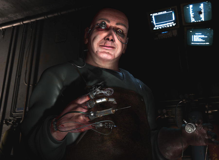
This image was my contribution to CG Talk’s Machineflesh challenge that ran from 16 March to 18 June, 2004. The task was to “create an image depicting a mechanically altered or enhanced organic lifeform”. I had a feeling that there would be a lot of cyborgs and warriors submitted, so I opted for a different approach – a surgeon.
|
November 02, 2005 | Stryker
This image was my contribution to CG Talk’s Machineflesh challenge that ran from 16 March to 18 June, 2004. The task was to “create an image depicting a mechanically altered or enhanced organic lifeform”. I had a feeling that there would be a lot of cyborgs and warriors submitted, so I opted for a different approach – a surgeon. Modeling the Instruments I started with a for me unusual approach, namely sketching with pen and paper. I’m not much of a drawing artist but the challenge required a concept sketch and I also realized that I would need to have a rather clear and focused idea of what I was about to do, so pen and paper it was. I tried several concepts before I settled on a surgeon with a mechanical lens instead of an eye and surgical instruments instead of fingers. I had a pretty clear vision of what I wanted and I knew that I had to get the instruments right in order for the image to work properly. The instruments would be attached directly to the flesh and wired to the surgeon’s neurological system , thus responding instantly to his movements. The instruments should also be removeable so he could replace say a scalpel with a drill if needed. My first priority was then to model five various surgical instruments and also figure out a way to attach these to the hand. Most of the mechanical modeling was done with Cinema’s primitives and lathed and swept splines . I tried to keep to two guidelines when making the instruments: they should look real and they should look functional . The scene does take place in some distant future but I didn’t want to create too futuristic instruments as I wanted the viewer to recognize each item. They should also look like they had a purpose and that they could actually perform that purpose. I needed five different instruments , all with some sort of connection to the medical world so I started browsing online catalogues from various medical suppliers, focusing on those dealing with eye surgery and dentistry . Finally I came up with a syringe whose hose or tube would be connected to a fluid socket on his arm; a saw ; a scalpel ; a pair of pliers/retractors and a miniature torch , also with a hose connected to a socket.
Each instrument was constructed around an identical base designed to fit the finger just in front of the first knuckle or bend. I relied heavily on Cinemas Symmetry object in the construction, as I generally only had to model one half and then the Symmetry object made sure the other half was identical.
The tubes running from the syringe and the mini-torch was made with splines and SweepNURBS . To fix the spline’s endpoints to the instrument on one side and the socket on the other I used a simple XPresso setup. This allowed me to rotate and move the instrument without the tube losing its position.
|
I’ve been dabbling in 3D since 1999 when I got a copy of Bryce. One or two years later I discovered Cinema 4D via a demo on a magazine cover CD and in 2001 I got Cinema 4D XL 6 on an educational license. I’m now using Cinema 4D R8.5and BodyPaint 3D R2, with Adobe Photoshopfor postprocessing.
I also tried as far as possible to give each edge a slight bevel or fillet as I wanted the edges to catch highlights . No angle in nature is 90° and not many manmade angles are exactly 90° either, and by giving the edges just a slight bevel the items immediately gains a more realistic look and will react more naturally to light. This can shoot the polygon count through the roof if one is not careful but I’ve found that flat bevels usually works just as good as rounded bevels, at least if the camera isn’t getting too close in the final render. |
|||


 Name : Anders Kjellberg


|
|
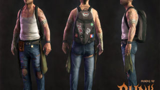
In my original concept I intended to show two hands, one complete (the left) and one with instruments (the right) so to save time I decided to model only one and then mirror it. I knew I had to make it rather detailed since I was aiming for a semi-realistic image in the end. I wanted to give not a photo-realistic impression but rather the impression that what the viewer sees might actually be true some day. This was the first time ever for me modeling something as intricate as a hand and I relied heavily on online tutorials and lots of reference images from 3d.sk . I set up my reference views in Cinema by mapping photos on planes and then started building the first finger. A Tube object with 8 rotation segments gave me the basis and general shape. I then used the Katana tool in Mesh Surgery to cut up the geometry and giving me more points to work with. Once I had one finger done I duplicated, moved and scaled it to get the other four fingers. The rest of the hand was sculpted from a simple Cube object which I merged with the finger geometry. The veins was a bit tricky to get convincing. Cinema XL 8.5 does not support n-gons and I wanted to avoid triangles as far as possible. Once again Mesh Surgery helped – its Scalpel tool allowed me to perform very precise cuts and the plugin Spin Poly helped me with “spinning” triangles into quads.
After the hand was done i mirrored it to get a right hand to work with. The instruments were to be attached between the knuckle and the first finger joint so I deleted all unnecessary geometry and bridged the hole. I then imported my first instrument and positioned it correctly, before I made some dents in the flesh where the supporting clamps would be placed.
|
|||
 |
||||


|
I also modeled the area where the tubes running from the mini-torch and the syringe attached to the wrist, and I played around with lots of different concepts before I finally decided on a design that allowed for torn skin with lascerated edges, with nuts and bolts and metallic stitches to keep it all together.
The XPresso described on the previous page was used to fix the tubes in position so I could freely rotate and pose the individual instruments and tubes withouit worrying about them losing their place. After the hands I continued with the next major part in the scene: the head.
|
|


|
|
All my head modeling always starts with the eye and the eye area. The first step is to model a very basic eye shape. A Sphere rotated 90° on the X-axis will act as the main body and by moving some points I get the flat iris section. The pupil is basically a hole in a real eye so that is accomplished by extruding the central polygons. The sclera and cornea is then modeled by rotating a Bezier spline 360°, making sure it fits very tight around the body of the eye. This eye will now act as reference when I start building the eyelids and face. The method I prefer when modeling heads is POP – poly-by-poly or point-by-point . I switch to Front view, create a new empty Polygon object and start Ctrl-click new points in the shape of the eyelid. These points are then bridged to form polygons which are sculpted around the the eye. The outer loop of points is selected and then extruded using the plugin Edge Extrude Pro to build up more defining shapes and this process is repeated throughout the whole head. Many prefer the box modeling method for organic materia, but I find that this technique gives me total control over the topology of the mesh, wich as far as possible consists of edge loops.
Details and wrinkles were added by using Mesh Surgery’sScalpel tool to cut and separate points then the Slide tool to slide the points into position. The right eye was replaced by a mechanical lens and the eyelids adjusted using the Magnetto fit it. At this stage I had the hands and the head all modeled and ready to go, so the next step was to texture them using Maxon’s BodyPaint 3D R2and Photoshop |
|||


|
Once I had as much reference images I could get, I started painting the textures, using a mix of photos and regular paint tools. Using the template it was pretty easy to rough out the features of the hand and eventually adding more and more details. The seams presented a problem, though, but BodyPaint’s Projection Painting solved that: I just projected a skin texture across the seam and then used the Eraser to blend the new texture with the old. The texturing of the instruments was pretty straight forward. I used mainly Cylindrical or Cubic projection modes and I tried to re-use as many textures as possible, letting various parts share the same bitmap. |
I brought the hand model into BodyPaint for UV-editing . I opted for an approach where I unwrapped the palm, the dorsal side and the finger stumps individually, an approach I probably wouldn’t choose today. I started by setting polygon Selection Tags for all areas I wanted to map individually and then used BodyPaint’s Interactive Mapping feature to separate and flatten the various sections. I also made extensive use of the Relax UV feature to get rid of overlapping polygons. Next step was to export a template of the UV-grid. I started by selecting all polygons I wanted outlined by using the Live Selection Tool . Then I set the brush size of the Brush Tool to 1 pixel and the colour to black. In polygon mode I then selected Layer > Outline Polygons , and my selection was outlined with a black 1 pixel sized brush stroke. I did the outlining on a new layer so I can hide it in Photoshop if needed. Finally, I saved the texture as a *.PSD-file by selecting File > Save Texture as , which gave me a layered Photoshop template to work with. For the hand texture I searched online medical databases for various skin diseases and I scanned images from medical textbooks found in the university library. My goal was to give the hand a skin that illustrated the pain in the machine flesh intercation (having all those instruments and wires attached to the human body cannot possibly be good for you!).
|


 |
 |
|
|
The head followed the same procedure as the hand: UV-editing in BodyPaint and painting (mostly) in Photoshop. I started by setting polygon Selection Tags for the areas I knew I would either like to unwrap separately, like the ears, and for areas I knew I wanted to hide, like the inside of the nostrils. Once I had all my tags in order i brought the head into BodyPaint and started Interactive Mapping it, using Cylindrical projection. The mesh had some serious overlapping problems so once again Relax UV came to my rescue. The ears were given a basic Flat projection and also these had some problems with overlapping polygons but nothing critical. I didn’t pay much attention to the top and back of the head as I kew these areas wouldn’t be seen in the final render. The template was saved as a 5000×3000 Photoshop file (later reduced a final size of 3000×1800 ) and using photos from 3d.sk and my private collection I started assemble the face texture. I made heavy use of the Dodge , Burn and Clone tools in both Photoshop and BodyPaint. A nice feature with BodyPaint is the way it integrates so smoothly with Photoshop. If I work on the texture in say Photoshop and save it as a layered PSD, I just have to reload the texture in BodyPaint to see it. If I work on the texture in BodyPaint and saves it there, I just do a Revert to Saved in Photoshop to get the new version.
I did the bulk of the texturing in Photoshop and the bulk of the detailing in BodyPaint. Raybrush painting allowed me to paint in realtime on the mesh and slight adjustments of the UV’s were only a tool away. |
|||||||||||||


|
The monitors and the gastubes were added to fill the space in the scene. I didn’t want to clutter it too much as I wanted all attention and focus to be on the surgeon, but I needed something. The monitors are as you can see pretty basic – a Cubein a HyperNURBSprovides the screen and the rest is mostly standard primitivesand extruded splines. The gastubes are also very simple: a primitive Capsule Objectprovides the body and the gear is mostly Oil Tankand Cylinder Objects. The cord is a Bezierspline defining the flow and a Circlespline defining the girth. Both are then dropped in a Sweep NURBS.
The texturing of the environment was kept to the bare necessities as most of it would serve only as a backdrop. To reduce the memory load many bitmaps were tiled and reused wherever possible. Most of the props are textured using standard mapping modes: the wall uses Flat mapping, the gastubes uses Cylindrical mapping and so on.
|
The enironment is very simple and basic. The whole scene takes place in a dark room, possibly in a cellar of some kind. The lighting is sparse, the pipes are clearly visible and the POV(point of view) is placed rather low. I started by adding a single Planeto act as a wall. This was then cut up to give room for a vent. The heavier pipes were boxmodeled after photos of the pipes in the cellar of our apartment building and the thinner ones are simple Cylinders.
Much in the scene depends on lighting and I wanted a classical type of “evil” lighting, namely to have the character lit from below. The traditional 3-point lighting rig places one main light above and to the left of the main character, one fill light slightly lower and to the right and one rim light above and behind the character. For this scene I started with this lineup but here the main light comes from below with the fill light and rim light coming from above.
All lights had Falloff enabled since it not only represents a “natural” light but also gave me the ability to control how much of the scene the cone or sphere of light would illuminate. All in all I used about 15 lights, mostly Spotlights but also a few Omnis .
|
|||


 |
||||
|
|
The challenge requirements for the final render size was at least 3636 x 2657and I knew I would have to render in passes in order to make it, especially since I wanted a slight DOF(depth of field) as well. The complete scene was quite naturally split up in a foreground (the surgeon) and a background (the room) so I saved one scene with only the backgroundand one scene with only the surgeon. Cinema 4D has DOF as a post render optionbut my computer choked when it came to this so I somehow had to do it in post. I used 10comm tools to Flushall materials and shaders from the background scene, enabled DOF in the Camera’sattributes and rendered a depth map. I also rendered a lot of alpha masksfor use in compositing, including the instruments, the hand, the glove the eyepiece and so on.
Once I had all my main renders and alpha masks I started working on them in Adobe Photoshop 6, my 2D application of choice. I created a single PSD file with all necessary image files as separate layersand started tweaking. I adjusted the Hueand Saturation, adjusted the Levelsand I used the alpha masks to separate and tweak elements individually. For the DOF I used the excellent Photoshop plugin Lenscare by frischluft. I already had my depth map from Cinema so I loaded that as source in Lenscare and applied a very subtle DOF. Finally I flattened the file and saved as TIFF, ready for submission.
3DM models creation |


 |

About The Author
You might be interested in