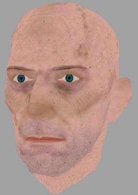
High polygon realistic character creation
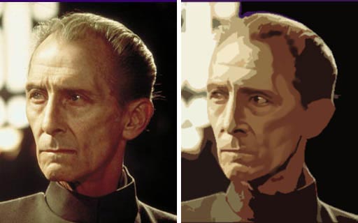
This is an overview of creating high polygon realistic 3D characters ( with a particular leaning toward the creation of the above model ). My inspiration for writing it, was that as a long time videogame artist used to working with real-time constraints, I wanted to learn high resolution modeling techniques, and I couldn’t really find all the info needed on the subject in one handy place. It’s a pretty barebones overview, since there is an entire books worth of material if everything were to be covered in serious detail. So I’m really talking about high level principles. It’s also geared toward capturing a likeness, since that makes up the vast majority of the work I do, but I wont talk about rigging or lighting or rendering, since they’re really not my areas of expertise, and entire tutorials in themselves. I’m attempting to keep it as non software specific as possible, but forgive me If I lapse into occasional Maya terminologies.
There are different surface types available to us achieve a high resolution model. Most of the time, I use smoothed polygons as opposed to true hierarchical subdivision surfaces. With true SubD’s you wont see any faceting associated with traditional polygonal geometry, since a subdivision surface is the result of an infinite mathematical refinement process to ‘smooth’ a model at render time. However, I wont go into why I prefer working with smoothed polygons here, but If your model is smoothed to a high enough degree, you wont see the aforementioned edge faceting under most circumstances. The basic concept of working with both surfaces is still one of ‘subdivision’, and the workflows are very similar.
Some of these are interchangeable, but generally speaking, this is the basic workflow:
1) Model
2) UV map and texture
3) Rig
4) Pose/Animate
5) Apply polygon smooth node
6) Render
Research and reference
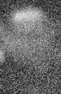
I can’t stress enough how important this phase is. Without well researched and considered reference, a likeness of a person is extremely hard to capture. You’ll need good front and side orthographic photographs, taken with a long focal length so that there is as little perspective distortion as possible. You’ll also want the head to be pointing as perpendicular to camera as you can possibly find.
Since, the angle of the head is looking down, this is a bad front ortho:
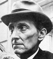
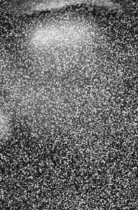
This, whilst not perfect due the head being turned very slightly to the right, is much better:

As long as you understand why your orthographic photo’s aren’t perfect, they will often do, since you’ll be able to compensate for whatever is not quite right in the photograph when you model.
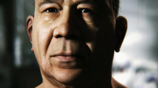
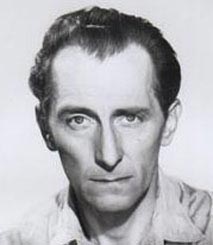
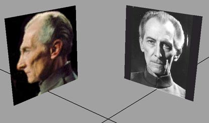
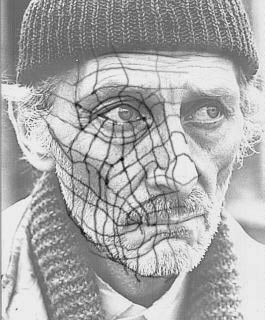
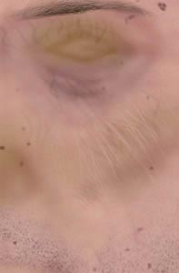
Along with good orthographics, you’ll need shots in between those 90 degrees, and you’ll also want shots taken under different lighting conditions. Certain lighting conditions are of more use to us than others when it comes to reference. Often the best is a diffuse lighting condition ( e.g overcast day outside ) since it’ll really tell us a lot about the bone-structure without hard shadows getting in the way. For example, the shot below was one of my most commonly referred to pieces of references of Peter Cushing, since the lighting conditions describe the complex facial bone-structure ( particularly around the cheek area ) quite clearly:
Get good with google image search! Try and think laterally when you’re looking for somebody and go off at tangents. If you discover a lesser known movie that an actor is in, search for that alongside the more obvious ones.
tip: look up an actors filmography on imdb.com
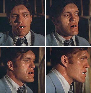
One of the most useful pieces of reference you can obtain however, is the head in motion. A common trick I often use, is to grab DVD frames from a movie of a head turning through 90 degrees and compile into an .mov. That way you can compare alongside your 3D model at angle increments:
If you don’t have a fancy DVD capture card, there is a more time consuming and less elegant method to capture frames: In your windows advanced display panel, turn your graphics cards acceleration from hardware to software. Now play the DVD, hit ‘print screen’ at the frame you want and then go into Photoshop and hit file new>edit paste. You can then save out the series of frames and compile them into a movie using your favourite 2D editing software. Premier, After Effects, Quicktime. Im sure there are some freebie ones too.
Ensure that your front and side ortho’s are square, and the right relative scale by lining up crucial features in Photoshop:
You can then go ahead and set up as image planes or simply apply to polygons in your 3D software. Make sure that your front and side images are square, and so are your polygons to ensure correct aspect ratio of the image. It’s worth assigning to layers so that you can toggle their visibility on and off quickly
tip : setup your modelling camera with a longer focal length to lessen the amount of perspective distortion whilst working. In Maya I always have the focal length set to about 90.
Subdivision Modelling
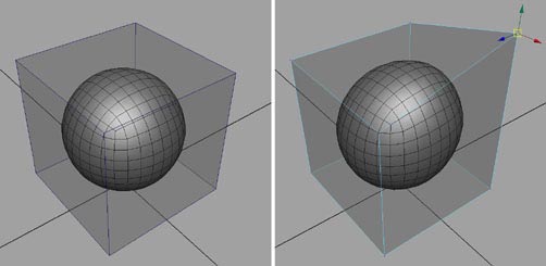
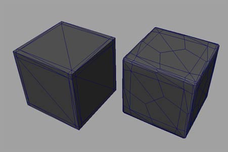
The heart of the concept is that we are no longer modeling at the vertex level, but instead modeling a ‘control cage’ that drives a higher resolution subdivided result. Here, the cube is the control cage that drives the subdivided version of it within. It’s the outer cage that we’re manipulating, not the subdivided result:
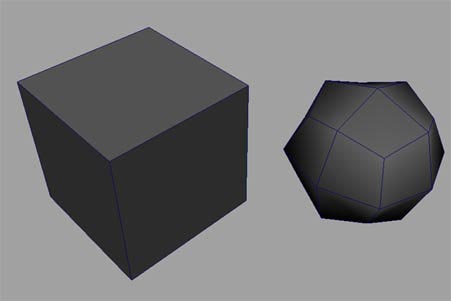
The biggest hurdle to overcome starting out with subdivision modeling, is how to control the output, since its not really a ‘what you see is what you get’ technique. There’s an element of prediction of the outcome involved which, with practice becomes second nature. You gradually begin to learn to predict how the smooth algorithm will affect the geometry. To explain, smooth a cube. Go to polygons>smooth. The settings should generally be set to subdivision levels1 ( or 2 or even more for a final render ), continuity 1, and smooth UV’s on. However, the result is simply an uncontrolled blob:
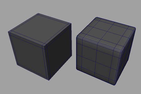
However, introduce extra edge rows close to the edges of that cube, and the smooth algorithm simply has no choice but to obey their existence:
It’s a hard concept to explain, so the best thing to do is to play with it. Some people like to use the ‘smooth proxy’ function instead of using smooth, which is the exact same as smooth, but it will automatically place your control cage and subdivided result on different layers so that you can quickly view the smoothed and unsmoothed versions. There are in fact many different tools and setups that people use in subdivision modeling workflow to distinguish between their control cage and its smoothed output. In Maya, the most obvious are simply ‘smooth and undo’ ( speaks for itself. quick and dirty ) and ‘smooth proxy’. But there are some great additional scripts such as smooth proxy side by side , CPS and I’m sure many more. It really comes down to personal preference.
There are often no strict rules in modeling, but loosely, these are some general requirements for successful subdivision type modeling:
1) The control cage should be where possible left as quads. The smooth algorithm simply works better with quads. It’s a mathematical fact that the smooth algorithm will always turn a model into all quads, but the more quads it has to deal with than triangles, the smoother the surface tends to be. If a control cage is 95% quads, then that’s doing OK. But more is better.
For example, If I smooth this triangulated cube, my topology becomes a mess ( and therefore how light bounces off the model will be equally messy ) :
But note that If I smooth this cube that is all quads, my outputted topology is much cleaner:
2) Try and keep the control cage as light as possible. And similarly, don’t let your mesh get too dense too quickly. Make sure you are fairly sure of your basic structure before committing to finer detail.
3) Avoid long narrow polygons.
4) Once you have subdivided your model, NEVER delete your history. You always need to retain a version of your model in ‘low res control cage’ form. Once you have subdivided, there are now way too many vertices to edit the mesh at the vertex level, rendering that mesh practically un-editable.
5) The principles of ‘edge loop’ modeling need to be grasped. Particularly with modeling faces. Very roughly speaking, edge loops represent muscle groups, but moreover, they represent the sub forms of the model that can be manipulated to most quickly define the overall silhouette and contours of the model. Refer to Bay Raitts page ( of Weta digital and Gollum fame ) to see an overview and far better explanation of ‘edge loops’ here
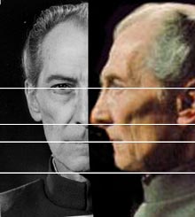
Moff Tarkin’s edge loops. Mouse over the image to see before and after the smooth algorithm is applied. Note how the resultant geometry is 100% quads even though some of the initial geometry is not :
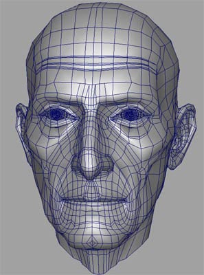
It’s worth noting that I built this geometry much before writing this tutorial, and when I look back on it I really don’t like the look of the abrupt termination of some edge rows in the middle of his forehead there. Whether or not it is the ‘done thing’ to leave n-sided polygons in a mesh thats intended for smoothing is an ongoing debate in CG modeling. There’s a huge thread on body mesh topology on cgtalk here. The thread starter was none other than Stephen Stahlberg, who sits firmly in the camp of it being OK to leave non quad polygons in the base mesh.
tip: If you decide you want to be really anal and ensure that your model is 100% quads ( and there are some reasons that you might. Some renderers insist on all quads for instance ) , export as an obj into Wings3D and Select>By>Faces With 5 or more edges. By the way, If anybody knows a way to check this in Maya I’d love to hear it!
tip by Robert Kopf : that it ISpossible to detect non quad faces in a mesh in Maya (beside using a script or so..) You can set the Polygon -> Cleanup funktion to select, rather than cleanup specific faces. Set the options to select Quads, inverse the selection and there you are, very useful to find and eliminate the last Tri or N-gon.
Modelling cont.
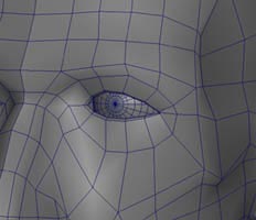
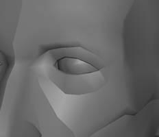
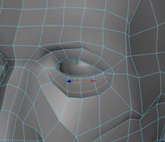
How you actually go about physically modeling is entirely up to you, and everybody I know seems to have a different way. Very generally though, whether you’re using Maya, XSI, Silo, Wings or whatever, the techniques and tools are the same. I tend to start with a cube. I then delete one side of the faces and instance mirror the geometry. That way Im working on one side and the other is being updated instantaneously. I tend to model ‘around the eye’ since the eye is just the most obvious place to start to me. I then simply draw topology onto the cube, tweak, and repeat. There are really very few tools that I use for actual mesh editing. Some kind of tool that enables drawing on the mesh ( in Maya it’s the split poly tool ) , extrude, bevel is really about all you need at the most basic level.
At the time I did the base for Cushings head, I did a time-lapse since it was for a speed modeling challenge. The video below is about 12 megabytes. You can click to watch or right click>save target as, and save the file. The video takes the model from cube to rough head shape ( about 30% done ) :
( temporarily unavailable due to lack of bandwidth sorry )
Now again, I created this model quite some time ago, so there are probably quite a few things that are much more efficient in my workflow now. I’m looking forward to lots of e-mails saying ‘urgh, I can’t believe you modeled it that way!’ :)
If you don’t want to d/load the 12 meg, here are some interim stages of the model during creation:
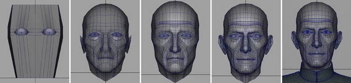
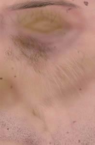
The ears disappear at one point, because I bolted on new ones from an existing model of mine. And why the hell not?! Ears are a bitch! Once the model reaches a certain point, it’s really just a case of implicit observation of the subject to get it to where you need it to be. Try and break up the face structure as you look at it into simpler planes. Here, I’ve applied a cutout filter in photoshop, and painted into it a little, to try and figure out the most basic facial planes:
and you can also try drawing edge-loops onto your reference to aid you:
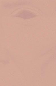
It’s a good idea get your basic topology ( edge loop structure ) nailed before fine details. It will be much easier to shift large chunks of geometry around thereafter . To explain further, this image has some early on basic edge loop structure in place:
Note that to keep a visual track of what my edge loops are meant to be representing, Im using hard edges:
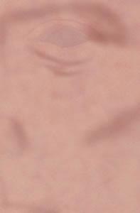
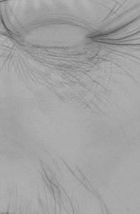
It’s after this point, that I can then worry about detail. The bag under the eye for instance, will need more loops within it to give it some form. Once I’ve added that edge I can push it out in Z to ‘fill out’ the eyebag shape a bit more:
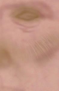
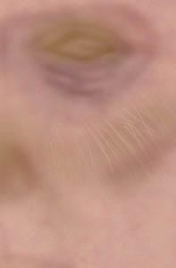
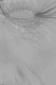
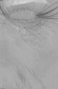
This is a commonly used topology for wrinkes. Note that the termination of the edge row at the side of the head ends in a quad:


Once you’re happy with your geometry, combine both pieces and stitch up the middle seam. You can then add some symmetry. Tarkin has a slightly broken nose for instance. Whether you intend to animate or no, it’s good practice to model the face in a fairly default pose, and then model a blendshape ( morph target ) as your target expression. Edit > duplicate ( making sure you are not instancing ) and tweak away. You can use the Maya 6.0 soft selection tool for morph target manipulation. It’s in the transformation tools section of the menu. Modify>transformation tools>soft modification tools. I actually prefer the awesome magnet script.
Once you’re happy with your target, pull down the animation menu, select your base mesh and then your target, and go to deform>create blendshape. You can now turn your expression on and off at will.
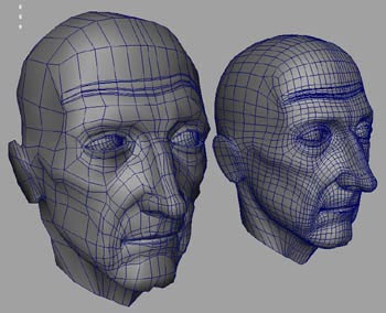
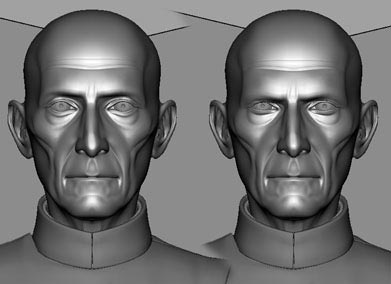
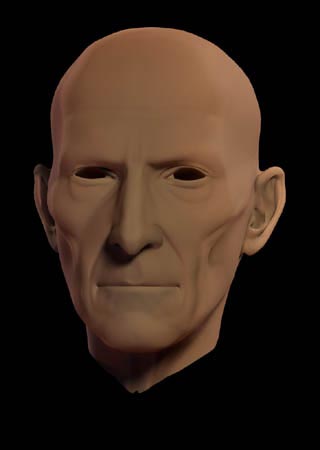
Default pose and somewhat disgruntled expression at right:
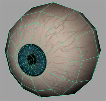
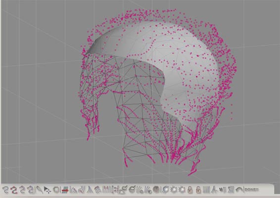
The eyeball model is pretty simple. It’s really just a question of replicating the actual structure of an eye. That way the way that light bounces off it later will be more convincing. Note how the eye has a concave iris, an actual hole for a pupil, and an outer sphere that acts as cornea with a convex lens. Note also that the geometry is all quads in anticipation of smoothing:
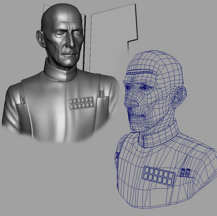
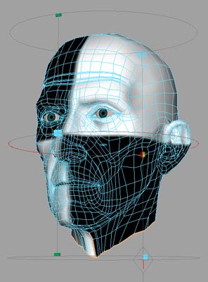
Final smoothed model with blendshape turned on at left and unsmoothed wireframe at right. Note from the wire that I’m less concerned about the occasional n-sided polygon in my tunic than I am the face. You generally don’t want too many n-sided polygons near the facial features that might be animated.:
Make sure that your model is left in its unsmoothed state before committing to the next stage.
UV mapping
A model will need good UV mapping co-ordinates before texturing. That might seem a little daunting on a high resolution model, which is exactly why the workflow of polysmoothing after rigging works so well. We are actually UV mapping our pre-smoothed low resolution control cage, not our final smoothed model. A cylindrical UV map is a good starting place:
 =
= 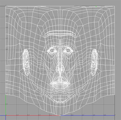
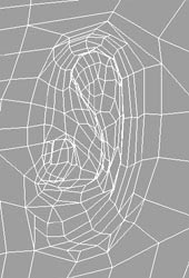
However, If you look at the flattened out UV’s top right, the basic feature layout of the wireframe, doesn’t really resemble the models face proportionally, and that will lead to UV stretching. Roughly speaking, the closer your UV layout resembles your polygonal mesh layout, the less UV stretching you will have. I’ve seen a failing to grasp this principle so often, that I feel compelled to spell it out rather obviously! :
Mouse over the image below. Note the texture swimming on the upper lip is due to the lack of resemblance between polygonal and UV layout. Note how once the UV co-ordinates more closely resemble the polygon layout the texture warping dissapears:
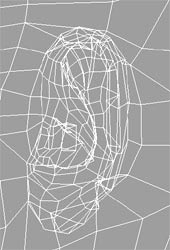
So, we need to spend some time getting our UV layout to resemble our polygonal layout as close as possible. You will also need to watch out for complex overlapping geometry too though, and it’s often worth doing a subtle ‘relax’ UV’s over the entire UV layout, or just certain areas like ears, so that polygons don’t end up sharing the same UV co-ordinates. Here is the ear on the left immediately after the cylindrical map, and shown at right after a relax UV’s operation:
Of course, this might tend to almost contradict what I was just saying about keeping the UV layout as close to the polygonal layout as possible, and technically speaking it does ( which is why I mentioned If using a relax function, to use it subtly ) , since the relax changes the UV’s co-ordinates in relation to one another. But when it comes to complex geometry, there really is no alternative, and it ends up being a compromise between the two concepts. After some scaling, moving UV’s by hand ( this is the bit where you’re glad your control cage is reasonably light ), and stitching, I ended up with this:
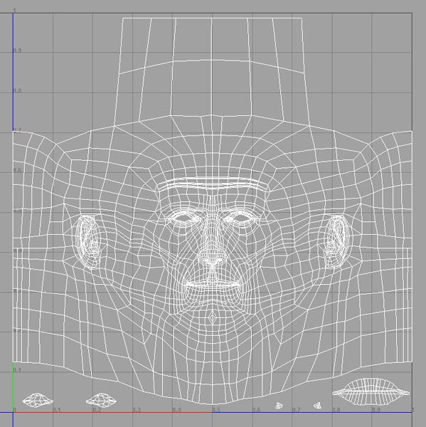
Note that areas like mouth/eye interiors have been moved aside for ease. Any game artists out there will be looking at this and thinking how horribly inefficient it is ( there is so much fat in pre-rendered CG! ) and of course I would UV this somewhat differently If it were destined for a game engine. I would mirror the side of the head for starters. But as I always knew this was destined for rendering, it’s not really an issue.
tip: in Maya, it may not seem immediately obvious how to quickly and cleanly separate specific UV faces amongst complex geometry ( i.e like I’ve moved the mouth interior aside in the above image ). The ‘cut uv’s’ function deselects the faces afterward which is a real pain. Solution: select the faces, hit flip UV’s, flip again to bring them the right way up, and then right click, select UV’s. Hey presto, you have all those faces you selected now selected as neatly separated UV’s.
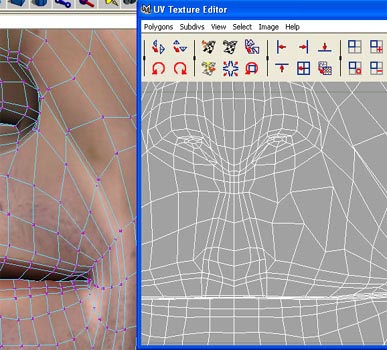
I’d then use the UV snapshot function to export this image as a targa and bring into Photoshop. A wireframe such as above however, can be a pretty daunting place to start for creating a texture map. Most CG packages allow for baking out a lit and shadowed map. In Maya, its called ( from the Hypershade ) the ‘Convert to file texture’ option:
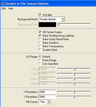
Using this function, I can setup a simple blinn shader and a couple of lights in the scene, and export an image like so:
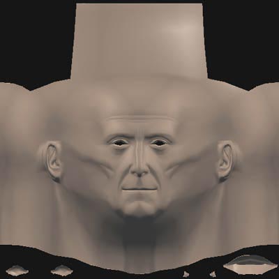
Now, whilst this doesn’t necessarily have to be used as a basis for a texture map, it’s a lot easier to ‘read’ than a wireframe for what facial features are what, and can be very useful as a reference layer.
Texturing and shading
As this model is destined for rendering, it’s going to need a lot more accompanying maps than simply a texture map. Along with the texture ( or colour, or diffuse, whatever you want to call it ), you will need a bump map, a specularity map, perhaps a translucency map. This can be taken a lot further to include all sorts of other maps, but for the Moff Tarkin image, I got away with just these. So, the tricky part, is working in a fashion that enables you to keep a relationship across all the maps. This is why all my maps I keep stored in the same layered .PSD. If you end up working this way though, be aware that this PSD can get huge in file size ( Moff Tarkins face PSD is over 100 megabytes ) , since you’ll end up with many many layers and need a resolution of at least 2048 pixels square. Get that ram you’ve been saving up for. I have 1.5 gig and could still use more.
t ip: get a wacom tablet! :)
So, in Photoshop I’ve created a .PSD with the exported baked shader as a layer, along with the UV layout as a layer. I’ve then sized it to about 2500 pixels square. ( uprezzing images is generally frowned upon but Im only using these as templates ) This resolution is perhaps a little overkill, but I wanted to be safe not sorry. I think for most uses 2048 is fine. For painting the colour map, I’ve blatantly stolen some concepts from professional sculptor Vance Hartwell. Check out his site here , as he has an awesome tutorial on how to build up the different layers that are needed to achieve convincing human skin. Using this principle, and examining images of Peter Cushing, this is how I built up the layers for the skin colour map:
1) Subtle stipple for skin pores ( very subtle, you might need to zoom in to see it )
2) A reddish mottle, vaguely meant to represent blood flowing under the skin
3) A red that’s meant to represent discolouration of the outer layer of the skin. Mainly sun damage. ( If painting sun damage think about where it would be most obvious. Generally the planes of the face that point skyward ) I have erased into the sun damage on the cheek to look like wrinkles.
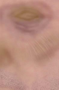
4) Purplish tone for bags under eyes
5) Beard stubble
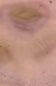
6) Moles
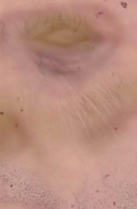
7) Veins
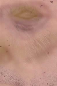
8) Random blotches
9) Eyebrow hair ( For a more realistic look however, I would recommend treating hair differently than painting on. See later in the tutorial )
10 ) Age spots
Texturing and shading cont.
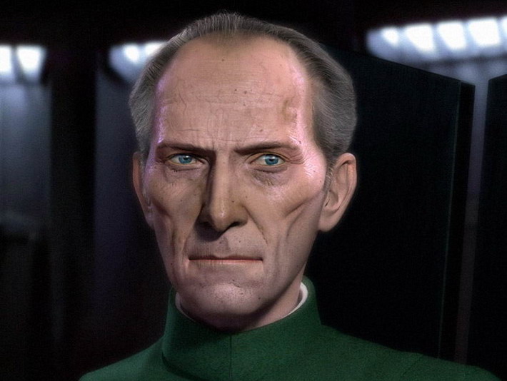
This is the resultant colour map:
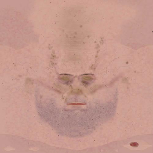
Applied to the model and using the ‘use no lights’ viewport option in Maya, it looks like so:
Attractive huh? Now, the next step is where having the bump and spec and colour all in the one PSD document comes in handy, since in order to create these maps and have them bear some relationship with the colour map, I start with my base colour stipple, and greyscale that to become my base bump like so:
1) Duplicate base colour stipple layer and convert to greyscale to use as base bump:
becomes 
2) Add wrinkles
3) Veins. Here, we are not painting new veins, but rather, duplicating our veins colour layer, and converting to greyscale and brightening to act as a bump vein:
4) Eyebrows. Again, were not painting these from scratch, but duplicating the colour eyebrows layer and converting for use as bump:
5) Moles. Once again, convert moles layer, so that their bump corresponds exactly to their colour:
Specular map
1 ) To be really clever here, we should probably use the same base texture pattern for skin colour base, skin bump and skin spec in terms of its patterning of skin pores. For some bizzare reason that I can’t recall, I didn’t in this case, but I think you’d have to be a pretty astute observer to notice. So starting from scratch, or from an existing base map you’ve made, create a pattern that looks somewhat like skin pores.
White receives maximum specularity or ‘sheen’ from light, black minimum. Look at some pictures of people to figure out the shiniest parts of the face:

2) Using the soft light brush, airbrush some areas to be shinier than others:
3) If painting eyebrow hair, add some specular by duplicating the colour eyebrow layer and converting to greyscale and tweaking:
Texturing and shading cont.
Now, all these maps have to go somewhere. Having a videogame Art background, I’m not by any stretch of the imagination an authority on complex shader networks, so I wont be writing anything up in detail. Very roughly ( and obviously ) speaking, in the Hypershade create a blinn shader, slot the colour map into the colour channel, the bump into the bump, and the spec into the specular colour. Set up a couple of lights and that’s usually enough to start doing some simple render tests:
That’ll give you a basic idea of how the various maps are working in conjunction with each other and what tweaks you need to make to them.
tip: Decide on your renderer early. Maya software and mental ray output quite a different look, and your maps values will look different between the two.
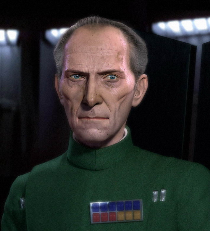
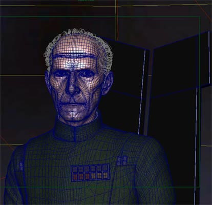
For more advanced skin shader questions, refer to the experts. Stephen Stahlberg has an excellent tutorial here , on the principles of shading human skin. Whilst I’d definitely recommend getting to grips with complex shader networks in the hypershade in Maya, many 3D apps have their own readily available skin shader either out of the box or in plug-in form. The human skin shader by Tom Bardwell freely available from highend 3D here takes the Stahlberg principle and provides a handy ready made shader network. What it does is several things. It creates a layered shader so that the highlights are on a seperate layer, it fakes translucency, it tints the specular colour slightly blue to counteract the tendency toward yellow hi-lights as discussed in Stahlbergs tutorial above, and it creates a ‘peach fuzz’ effect. With everything in place, some of the render tests were looking good but the skin was still looking a bit ‘solid’. I played with a few Sub surface scatter shaders and for good results I wholehertedly recommend the Diffusion SSS shader . ( it only works with mental ray. Try the lightengine shader for Maya software ) I rendered out SSS as a seperate layer and composited with the previous render in Photoshop:
I’d by that time been playing with Joe Alters plug-in ‘Shave & A Haircut’ at work and found it to be pretty nice. The real power is in the hair styling UI. But it also requires various hair maps in the same way that Maya fur uses them for density and cut etc. I also found it easier to apply the hair to its own piece of geometry flagged to not render, as opposed to direct to the head:
I created an image that mimicked the Death Star interior, to use as an environment map to place on a sphere in which to contain the whole scene. Final wireframe scene:
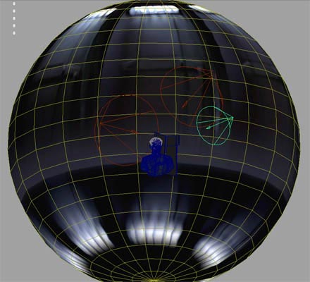
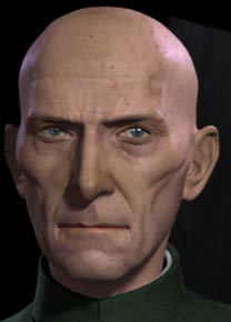
Refer back to the first page for the final image.
Go here for a handy links page on all things related to this tutorial.
That’s about the size of it. Feel free to bug me with any questions or certainly point out any better workflows or glaring errors.


About The Author
You might be interested in