How to make realistic trees with SHAG: FUR
Step 1: the making of the trunk and the crown of the tree
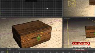
Let’s start with the trunk of the tree. This is not a tutorial about mesh modeling that’s why I am not going to explain it in details.
The Trunk
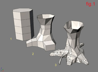
Make a cylinder. Then convert it to editable mesh, and with the help of extrude, bevel and moving the vertices try to make the model look like fig.1
The Crown
There are two ways to make the crown:
The first way is to make your own model but it takes longer.
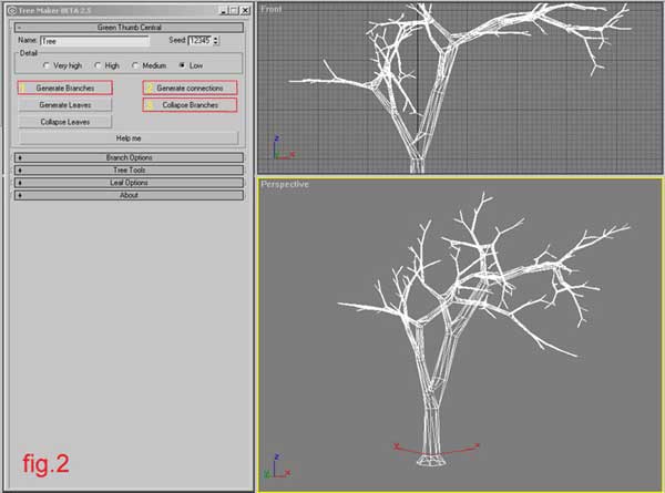
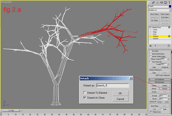
Here I am going to explain the easiest way. In my case I used the free script treemaker by Shawn Lewis http://www.scriptspot.com. I created a tree with the default parameters. From the script’s menu I converted it to editable mesh. On polygon level I selected the branch/es/ and detached it as clone giving it a name for example “branch_1”; (fig. 2, fig. 2a)
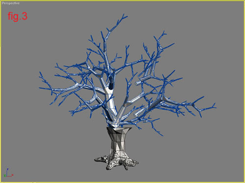
Then you delete the mesh saving only the clone (branch_1), and using rotate and clone operations arrange the crown of the tree (similar to fig. 3).
Step 2: The fur part
Attach all of the branches in one object. Go to polygon level and make a random or exactly chosen selections – it depends of what you want to achieve. In my case I selected only the ends of different branches. Give material ID number to the selection/s/. If you are going to place more than one fur on the object use different selections with different ID’s.
A similar result is shown at fig. 4

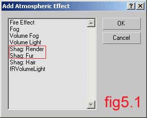
Then close the Edit Mesh menu and go to the Environment panel. Press the Add button and select Shag:Render and Shag:Fur (fig. 5, fig. 5.1)

In the Shag:Render field uncheck Geometry Larger Than. When checked, this option will alarm when the geometry is over 50000 faces (by default). You can increase or decrease the number of faces, but I prefer to turn it off. (fig. 6)

Then you go to the Shag:Fur field, click on the Pick button and then in one of the viewports select the crown. After that you will see the whole object covered with fur. Press the Face Level button and tell the fur where to be placed. (fig. 7, fig. 7.1)

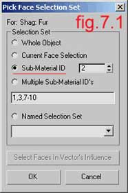
There you choose Sub-Material ID and type 2 in the field. If there is only one selection you can select Current Face Selection, but in more complex objects it is better for you to choose between Named Selection, Sub ID or Multiple Sub IDs. In the viewports now you can see that the fur is in the right place.
Then you go down in the fur menu where the parameters for Length, Thickness and Density are. For length type 50.00, for thickness type 2.0 and check the box named Flat in the Section field. For density type 0.1 (fig 8.0)

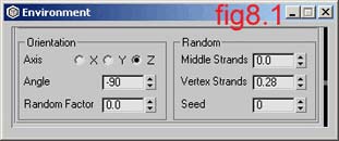
If you want to create a more chaotic look of the crown use the Orientation and Random options (fig 8.1)
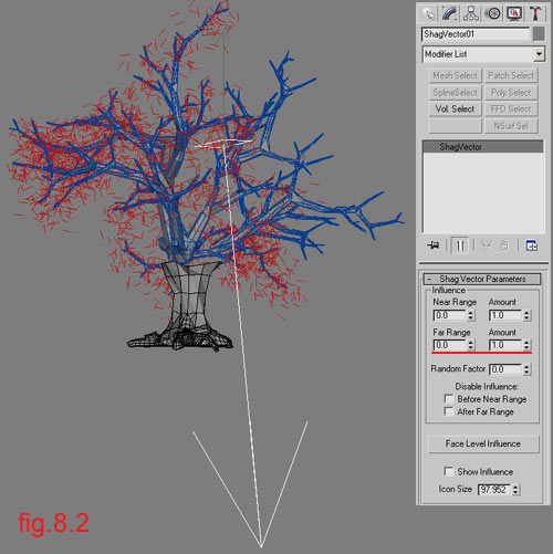
If you want to simulate gravitation use the Shag Vector. Select it from the Helpers menu. Place the vector and type for Far Range 0 and for Far Amount 1.0. This makes the range of the vector unlimited. (fig 8.2)
Then you go to the fur menu in the Leaning and Bending fields. In the Leaning section press the Select button and choose the vector. Then play with Amount, Max Angle and Random Factor. (fig 8.3)

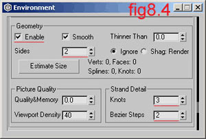
Go up in the field Geometry. Check Enable, make it 2 side and type for Knots – 3 and Bezier steps – 2. (fig. 8.4)
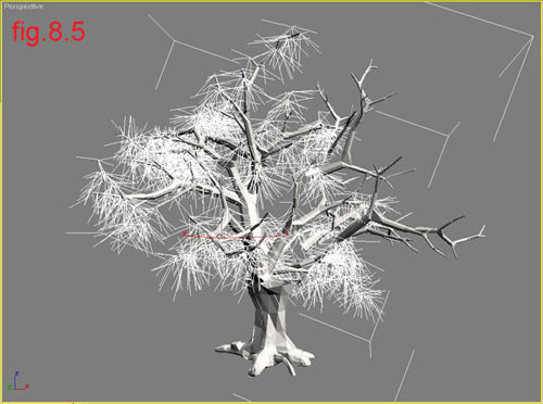
If you made it right through here you will see something like fig. 8.5
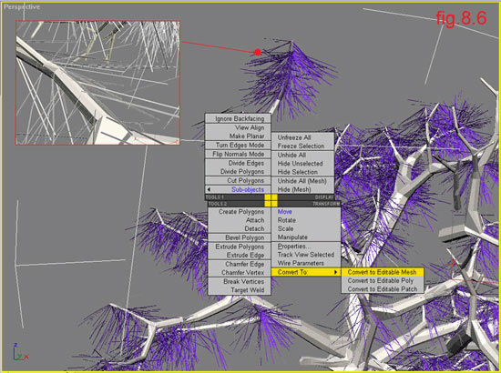
Select the Fur object in the viewport and with right mouse click convert it to an Editable Mesh and give it a name “subbranches”; for example (fig 8.6)
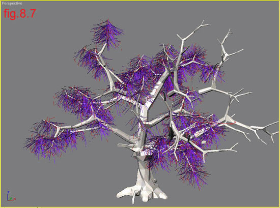
Then you go back to the Environment menu and add a new fur. Press the Pick button and select the “subbranches”; object. You will see a result similar to fig 8.7.
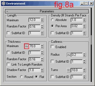
Now hide the “subbranches”; – you don’t need it anymore. Name the new fur object “leaves”; for example. Now you need to repeat the whole operation that you made for the “subbranches”; figures (8.0, 8.1, 8.3 and 8.4).
Use the following parameters:
Length: 12.00
Thickness: 70.00
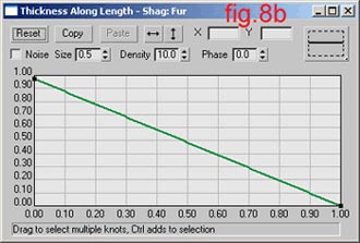
Next to the thickness parameters you have a button /fig 8a/. Left click to enable it, with right click you open a panel where you can edit the curve / fig 8b/.
Make the section flat again.
And for Density type 0.01.
Feel free to play with Random and Orientation parameters (fig. 8c)

A good feature of the plugin is:
When you select a fur geometry in Max’s Modify panel, a menu appears in which you can convert the geometry in mesh (but that does not collapse it). With this feature you can see the deformation of the fur object in real time (see the figure below).

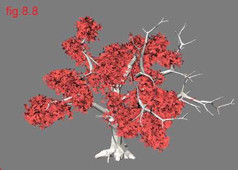
Check Enable geometry, make it 2 sided and type minimum parameters in Strand Detail (fig. 8d)

Then you can convert the geometry to an Editable Mesh but this will slow down the work on the scene. If you want to animate the tree don’t convert it. The result of this is shown on fig. 8.8
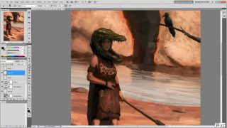
Step 3: The color part
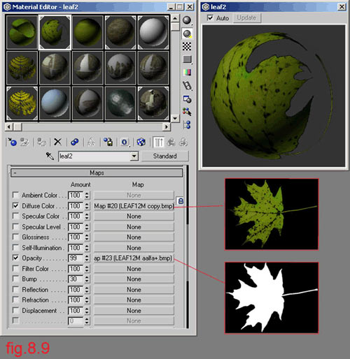
In Material editor make a standard material. For Diffuse use a map of leaf and for Opacity use the same map but in grayscale (fig. 8.9)
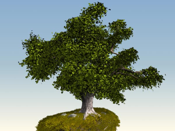
Then assign the material on the fur object and make a test render (fig. 8.9.1)

The tree is almost ready. Repeat the operation in other parts of the crown. It’s better to use different parameters for the leaves to create various results.
Here is a sample part of the scene branch with leaves and textures – Shag: Fur required
Download Trees_With_Shag_Fur_Sample_Scene.zip (368 KB)
And the final result
Download [368 KB]
This is for now, more tutorials how to make different kind of trees or plants coming soon
THE END


About The Author
You might be interested in