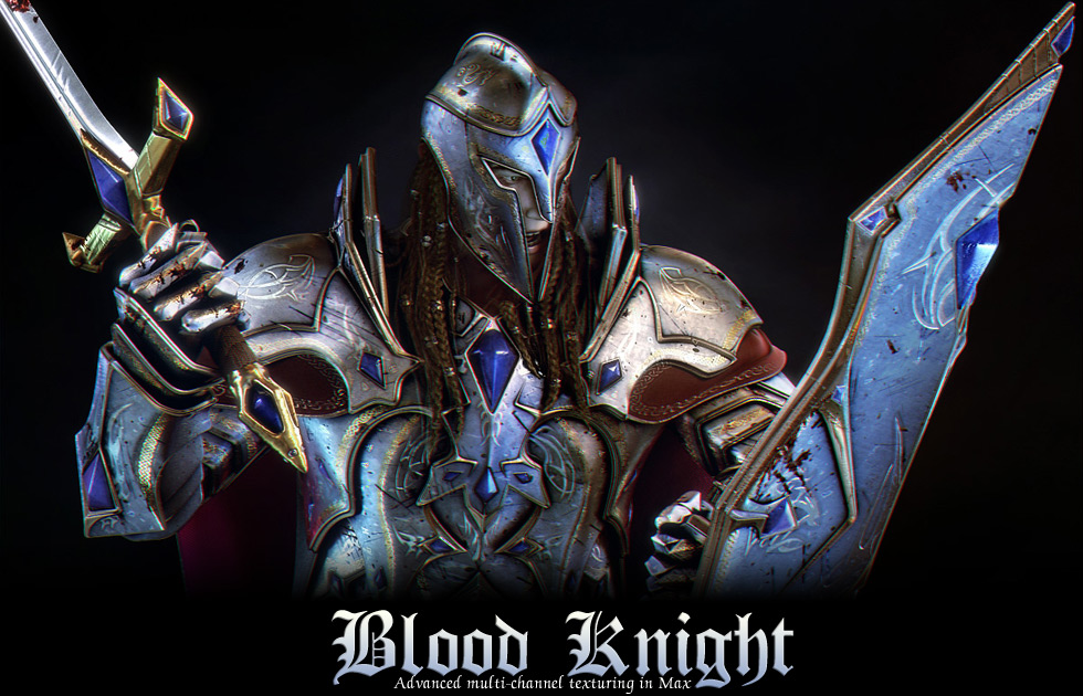
Making of Blood knight
Ziv explained the unique texturing method which he used in the image Blood Knight created in 3ds max
Advanced multi-channel texturing in MaxOver the years I’ve learned and developed my own solutions and methods for complex texturing. The blood knight is the second of several characters I’m making and since he’s the one who experiences the battle up close and personal more than the others, I’ve decided that with him I will try to push my methods to add many details such as dirt, scratches, stains, blood, decorations etc’ much further than before in a method I like to call “multi-channel texturing”. My main focus on this character was the texturing / shading and in this tutorial I will share the process, considerations and a few other tips. Click here to download a test animation I’ve rendered to check how the materials react to different lighting setups. Multi-channel texturing – general idea, pros and consThe method I refer to as Multi channel texturing takes advantage of the ability to have many different map channels (in other softwares like Maya this is referred to as UV-sets) for the same object while it’s material is made out of many maps mixed together using masks with these map channels. The end result of this is that all the armor’s parts (over 40 different objects in the blood knight case) use the same material with just a few textures, as opposed to the “classic” texturing method in which you end up with many materials and hundreds of texture files (assuming each material will have several textures for color / bump / specular etc’).
Pros Cons |
STEP1 – Getting started – mesh preparation and Base materialThe base of this workflow begins at the modeling stage. The modeling process of all the armor’s parts was pretty similar: Step1 – work on the base shape of the armor’s part and prepare it’s topology for the details to come with as few polygons as possible (note that It may seam I used more than the minimal amount of required polygons but that is only because the end result required many sharp corners) to be able to easily modify it later on if that would be required. these polygons receive polygon ID 1. Step2 – Add Shell modifier to the model and set “Override Edge Mat ID” to 2. Once I decide the model’s base shape is final I collapse the shell to editable poly and modify the edge polygons a bit further as I find fit. Step3 – Take advantage of the prepared topology from step 1 to extrude the polygons in (to prepare the socket), Change their ID into 3 and then extrude them out to create the diamonds. Step4 – (optional) In some of the armor’s parts I’ve used another polygon ID – 4 for silver when I wanted more variation in the materials, this was also used for the sword’s blade. Throughout the modeling process I’ve had the base material ready for early testing, the base material is made out of 100% procedural maps and that is why it did not require me to unwrap the model as I was still working on it, the complex final stage of the texturing only came once I’ve decided modeling was done. The base material is made out of a Multi sub object with 4 ID’s 1- The main armor’s metal, 2 – The armor’s outer gold, 3 – The diamonds, 4 – Silver. I will focus this tutorial on the main armor’s metal.
For the base main armor metal material (ID 1) I thought of going for a standard material But decided to go with Mental ray’s A&D shader because it supports blurry reflections, A decision that made the material pretty heavy but look good :) The parameters I’ve decided to add maps to are Diffuse color, Bump, Glossiness, Reflection color. The idea is to add MATCHING maps with different color brightness levels to these parameters while keeping this in mind brighter colors mean: The map I’ve created for these parameters was made out of a few procedural textures, this made it easy to control the brightness level of the colors for each of the parameters – for example – in one of the specific textures, I used a bright color for the dirt in the diffuse color but changed it to dark in the bump map to make it cause an inner dent and also dark in the reflection color because this dirt is supposed to be less reflective then the armor’s metal. Making the base material with procedural textures is also good because a simple combination of a few procedural textures can hold a very high res detail level at a low resource cost and every single armor part will have different detail features (as opposed to mapped texture files which tend have duplicated features look). i’m not gonna go through all the specific parameters of each map because many different combinations can work just fine and it is all a meter of trial and adjustments, you can look at the shading network chart I’ve made to get the idea. My advice for this step is to add one map at a time, and always make sure you keep track of the contribution each map gives to the details. It sometimes helps to copy the specific map you are working on to a clean new material and apply it to the model just to check how it fits it. TIP: I often use an Ambient occlusion map as a mix map at the base of the diffuse color for added depth detail – for the white color I simply add the maps I was gonna use anyway and for the dark color I add some noise maps for “corner dirt”. |
Adding a mix level procedure and a few material editor notesBefore we go further, I just wanna share a few insights about the material editor and explain the process of adding more and more details to an existing map generally – these things will be most relevant for the next step. General idea of the process of adding another mix levelSo we have a nice base shader by now but we wanna start adding more specific details to maps we already have in the diffuse color / bump / glossiness / reflection color, how can this be done? The answer is to add another mix level to these maps and then add another mix level and another – there is no limit to this except the more levels we add the more complicated it will get, this is why it should be done in an orderly fashion and this is how it should be done: 1) Go to where the map you want to add a mix level to is located, right-click and CUT that map. for example – if the map is in the diffuse color slot then we go to the diffuse color map slot in the base material. another example – if the map is inside a mix, we go to that mix.
2) Add a new mix map where your map was, right click on the map1 slot and paste your original map back. after this step your material should act the same as it did before, you’ve simply prepared your map for additional details.
3) Add a black and white bitmap in the mask slot and name the mix map accordingly to the mask. for example – if you added a “blood stains” bitmap you should name the mix map blood stains. naming your mix levels will help you later on when the material starts to get complex. The black pixels of your mask represent where your original map will be and the white pixels represent the new color2 / map2.
4) adjust color2 / add a new map to map2 slot of the mix. for example – blood: in the diffuse color you might wanna add a red noise map there, in the reflection color you might wanna add that same noise map but with a darker shade of red since the blood is dry and less reflective than the armor’s metal,in the bump map you might wanna use that same noise map but with bright grayscale colors since the blood stains act as OUTER dents.
5) Go to the mask and give it a new map channel. This is the last step in the material editor. since you’re going to use several different masks you’re going to need to use different map channels in order to create different UV’s to map each mask separately. I’ll explain a bit further about map channels next.
Map channel (material and uv map / unwrap) What are map channels? Output benefitsBack to the material editor. Since we covered most of the process in the material editor, In the next step I’m going to focus mostly about how to work with the UV’s but I would like to first share how I go about doing most of the tweakings once I’ve already added some mix levels. Through the output tab you can easily override and adjust the weight each and every map gets in the mix levels. It allows you to manipulate the colors and sometimes “override” the limit of the contribution a map gives. I will go quickly through the parameters: Output amount – gives control to override the amount of contribution the map will have to the material. RGB offset – this basically controls the darker colors of the map. I often give this parameter values below 0 to strengthen the contribution of the darker colors to the material. RGB level – this basically controls the brighter colors of the map. Bump amount – this parameter is very useful to tweak the contribution to the bump for each map. it has effect only in the bump slot, obviously. Enable color map – this one gives a bit further control to most of the things mentioned before but here you can manipulate the map itself and it’s colors. it is very useful when you want to use the same bitmap but with some variations – it eliminates the need to create new bitmaps just for that or going to photoshop just for some basic color adjustments. Working with the limits of “show map in viewport”One last material editor note before we move on. Max is very limited in it’s ability to show how the maps sit on the model in the viewport – it often doesn’t show the correct scale of procedural maps and when several maps are mixed together it can’t show the combined end result in the viewport. That is why for the next step you will always need to go to the specific mask you are setting the UVs for and turn “show in viewport” from there. In any case, doing a test render every now and then to see how everything combines on the model is a must to progress correctly. |
STEP2 – Mixing in details in different map channels and adjusting them on the meshEverything done so far can be considered as preparation for this step, this is the main step for this technique. I’ve explained how I go about adding more mix levels to the material editor so now I’m gonna focus on what I’ve done with the uv’s for each mix level I’ve added.
Map channel 1 – blood and general maps
Map channel 2 – Side decorations / diamonds’ gradient
In this tutorial I am focusing on the shading of the armor’s metal material but I just wanted to mention here that I’ve also used the same map channel 2 unwrap for the diamonds – in the diamonds’ material I’ve placed a radial gradient map in the “extra light” slot to give them extra subtle depth, I went through every object that had diamonds in it and in the same map channel 2 unwrap modifier that was already there I’ve selected the diamonds uv’s and manipulated them around one of the tiles of the gradient (and not necessarily in the center of the uv’s to avoid cluttering).
|
|
Map channel 3 – Symbols
So now we go again through every armor part, add another unwrap modifier and set it to channel3. First step is to select all the uv’s, scale them down and take them outside of the uv box (which should be enough to “make a clean start” since the tiling is turned off). The idea now is to select the polygons that will have a symbol, hit planner and and manipulate the uv’s until you are happy with how the symbol sit’s on the model. Again, immediate viewport feedback makes it possible to nicely “deform” the original shape of your symbol to fit the shape of your models more “naturally”, this also helps avoiding having a cloned look when using the same shape several times. (take a look for example at how much the big shape on the helmet is deformed from its original texture to fit the flow of the helmet). Map channel 4 – scratches
For most of the armor’s parts I’ve simply placed a UVWmap modifier with map channel 4 and did a quick move/rotate/scale tweak to the gizmo to determine how the scratches fall. Result
Related Links: |


