Creating High Res Polygonal Models
Outline
I. Overview
II. What Are Smoothed Polygons?
III. Why Use Smoothed Polygons?
Advantages:
1. Simplicity
2. Intuitive interface (no stitching).
3. Speed of production.
4. Built in level of detail.
5. Single texture map for entire character.
6. All areas of the texture will be proportional to each other.
Disadvantages:
1. Requires UV layout
2. Cannot add or remove edges after laying out UVs with autoColor.
2. Resolution may not be high enough for some formats.
3. Less control over tessellating than with other surface types.
4. Doesn’t work well with Maya Fur.
5. Texture seams.
IV. What technical problems are associated with smoothed polygons? How can I use History and MEL scripting to fix these problems
Problem 1
Too many vertices to skin the mesh once it is smoothed
Solution 1
Skin the low res mesh and add a polySmoothFace node after the skinCluster. Any blendShapes must come before the skinCluster
Problem 2
Poly faces with more than 4 vertices can produce bad results.
Solution 2
Model using Quads and Triangles.
Problem 3
UV distortion occurs after adding the polySmoothFace node.
Solution 3
Use projection nodes after the polySmoothFace node to lay out UVs on a reference object. Use MEL scripts autoColor, autoProject, and autoShellAssign to speed up the process.
V. Handing your model over to a character setup artist.
1. Production pipeline.
2. Merging the UV reference file with the setup file.
3. Hiding and locking the UV reference
Creating High Res Polygonal Models.
I. Overview
This tutorial will concentrate on how to use smoothed polygonal geometry to create high res models in Maya 4.5. We will be going over the advantages and disadvantages of this type of surface when compared to Nurbs or SubD surfaces. We will cover what sorts of technical challenges smoothed polygons present. We will use custom MEL scripts and History to overcome these challenges on your character model. Finally we will cover how to implement this type of modeling in a production pipeline. And I will show some tips on how to work with a character setup artist to merge your final polygonal model and textures into a well organized character reference file.
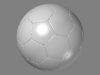
II. What Are Smoothed Polygons?
Smoothed Polygons are a low res Polygonal mesh with an adjustable polySmoothFace node in their history. To create smoothed Polygons use the Polygons – Smooth command in the modeling menu set of Maya. A popular technique is to use a low res mesh to control a High res mesh by connecting their shape and smoothing the result. There are also several free MEL scripts available to edit polygons in this manner Such as connectPolyShape by Dirk Bialluch. Or you can simply edit the low res mesh, add the polySmoothFace, and use the deleteInput MEL script to remove the smooth when you want to reedit the low res mesh.
The resulting mesh is still just polygons. However it will now be much denser and will have a polySmoothFace in it’s history. By using the polySmoothFace node you can create a level of detail which would be difficult to attain simply by adding edges manually. You should not move any vertices on the mesh after it has been smoothed.
Note that there are now 2 different smooth algorithms in Maya 4.5. The exponential setting works best with the scripts we will be using in this tutorial. I will be using the exponential setting for all the examples.
III. Why Use Smoothed Polygons?
Advantages:
1. Simplicity.
Polygons are the oldest type of geometry in 3D computer graphics. What you see is what you get, There is no tessellation or parameterization necessary. It takes less computation to calculate a flat plane made out of polygons than one made out of NURBs.
2. Intuitive interface.
Most artists can pick up modeling in smoothed polygons within a few days. Because the mesh is all one piece tangency between patches is not an issue. Stitching is not necessary. During the modeling process edges and faces can be added or removed quickly and easily. Although it is always a good practice to start out with the general shape of the model and continuously add detail The order in which geometry is created is much less precarious than with a Nurbs model. Where Nurbs Modeling requires a high degree of practice and skill to learn the correct order of steps in Modeling. Modeling in Polygons is more like fighting your way out of a wet paper bag.
3. Speed of production.
Models can be built much quicker in smoothed Polygons than in NURBs patches. Most Character Models take between 1 and 2 days.
4. Built in level of detail.
The divisions attribute of Maya’s polySmoothFace node can be adjusted at any time. This creates a built in level of detail which can be adjusted depending on the distance from the camera to the model.
5. Single texture map for entire character.
Using a polygonal model allows for the use of a single texture map for the entire character. This makes working on file textures in Photoshop much more simple and intuitive than working on multiple texture maps for a patch model.
5. All areas of the texture will be proportional to each other.
Using the custom MEL script autoProject we can keep each shell in the UV texture editor proportional to each other. This keeps the scale of texture maps consistent across the entire surface.
Disadvantages:
1. Requires UV layout
NURBs patches already have UVs embedded into their geometry. Provided that a model is well built in NURBs a texture artist can begin texturing as soon as the modeler hands him the finished model. Before smoothed Polygons can be textured an artist must go in and manually create UVs this generally adds anywhere between a few hours to a few days to the production process.
2. Resolution may not be high enough for some formats.
Despite all efforts to pack the UV texture editor tightly and use areas of a map more than once the UV map of a smoothed polygonal model almost always contains Unused space. The result is that Texture maps on a smoothed polygonal model must be larger than maps on a Nurbs model to achieve the same amount of resolution.
3. High poly count on smooth level 2.
Using smoothed polygons you have much less control over the smoothness of the mesh than if you used NURBs. On smooth level one the model may appear slightly faceted. Smooth level two however increases the face count on a model exponentially and often overshoots the number of faces that is actually necessary.
4. Doesn’t work well with Maya Fur.
This type of model just doesn’t work well with Maya Fur. The ability to brush the fur in an intuitive manner is severely compromised on polygonal models. NURBs models are far superior for use with Maya Fur.
IV. What technical problems are associated with smoothed polygons? How can I use History and MEL scripting to fix these problems
Example File: CylinderSkinExample_01.mb
Problem 1: Too many vertices to skin the mesh once it is smoothed.
Once you smooth a polygonal mesh and delete it’s history it becomes extremely difficult to bind that geometry to a skeleton. Although it is technically possible to set skin weights on all the vertices of a smoothed mesh it would be extremely labor intensive and inefficient.
Solution 1: Skin the low res mesh and add a polySmoothFace node after the skinCluster. Any blendShapes must come before the skinCluster
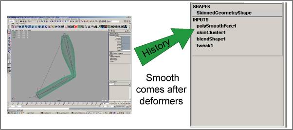
One solution is to skin the mesh before it is smoothed. This allows the character setup artist to only set weights on the much lighter low res mesh and smooth the geometry when he is done. Any blendShapes must be added before the skinCluster.
Problem 2: Poly faces with more than 4 vertices can produce bad results.
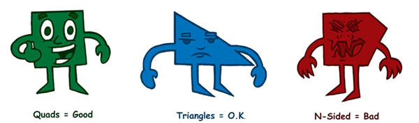
Faces with more than 4 edges or N-sided faces will cause unpredictable results when they are smoothed. Even worse when they are animated they may cause popping in the mesh.
Solution 2: Model using Quads and Triangles.
For this reason it is advantageous to model primarily in Quads and Triangles. Use N-sided faces as sparingly as possible. Definitely try to avoid these faces in areas that will be deforming heavily such as elbows, knees and the area around the mouth. The MEL script quadChecker can be used to color each face on a polygonal object based on its number of edges. Quads are green. Triangles are blue. And N-sided faces are red.
Problem 3: UV distortion occurs after adding the polySmoothFace node.
Example file: sphereExample_01.mb
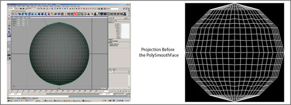
If you look in the UV texture editor when you add a polySmoothFace node to your mesh you may notice that the position of your UVs stays the same and the edges created by the smooth subdivide the preexisting edges. This is a problem. The UVs you now have are confusing in that they look similar to what a good UV set would be. However on closer inspection you will notice that they are no longer an accurate representation of your mesh. The surface you now have is curved while your UVs remain straight. This results in UV distortion. The extent of this distortion can range from very slight to severe depending on the original geometry of your mesh.
Solution 3: Use projection nodes after the polySmoothFace node to lay out UVs. Use MEL scripts autoColor, autoProject, and autoShellAssign to speed up the process.

By using polygonal projections after the smooth node we can eliminate this distortion. Because the projections come after the smooth in history they will automatically update when the smooth level is changed. This will create an accurate representation of the surface we will eventually be painting on. It also will create a UV map that will automatically update on any smooth level.
If the model you are painting on is totally flat this process is going to be easy. You will only need one projection. But how can we deal with a curved model containing faces that point in multiple directions. Won’t there be texture stretching in areas that face away from the projection?
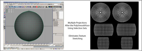
We will need multiple projections coming from different directions to eliminate texture stretching. Faces need to have their UVs created by projections coming from the most advantageous angle. Faces with a normal facing down the positive Z axis need to be projected from the positive Z direction. Faces with a normal facing down the negative X axis need to be projected from the negative X direction.
But how do we determine which faces get included in which projection? We need a way to pick faces on a complex polygonal object and tell Maya which direction we want them to be projected from. A common way to do this is to smooth the model and then select faces on the resulting high res mesh and project onto them. Selecting these faces is difficult because of the density of a smoothed polygonal mesh. In addition the UV map created will function on only one smooth level eliminating the built in level of detail we created by adding the polySmoothFace
By creating selection sets on the low res model before the polySmoothFace is added we can break up the model into areas which will use different projections. After the model is smoothed these selection sets will include the new faces that result from the originals. It is easier to use this method because there are less faces to select on the low res model. Because the selection sets will update when the smooth level of the mesh changes the built in level of detail is preserved.
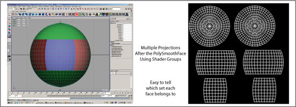
A disadvantage of using regular selection sets is that there is no quick way of telling which faces are included in the set without selecting it. For this reason it is advantageous to use a special type of set called a shader group to make our selections. The main advantage of shader groups is that they are linked to a shader which can change the color of the faces in the shaded view. This can give artists a quick visual representation of which faces are included in which set. Assigning a shader to a face automatically forces that face into the shaders corresponding shader group. Also a single face can only be contained in a single shader group. Assigning it to another shader removes it from it’s current shader group. This is an excellent way to set up face selections to be used with projections
Manual process for laying out UVs on high res polygonal models using shader groups as selection sets.
1. Assign different colored shaders to the low res mesh based on which direction they are facing
2. Smooth the mesh to level two using the polySmoothFace
3. Select the contents of each shaderGroup one at a time and project onto it from the most advantageous direction.
4. Set the polySmoothFace.divisions attribute back down to zero
5. Select the projections one at a time and move them apart. Try to pack the shells in as tightly as possible.
6. Assign a single shader to the entire mesh at the object level.
7. Delete unused nodes.
This process works fine and can definitely be used to create UVs on smoothed polygonal characters. However going through and assigning shaders to each face on a model by hand is labor intensive and monotonous at best. Creating projections from these shaders one at a time again is repetitive and slow. By using MEL to do these tasks for us we can spend more time painting textures and less time laying out UVs.
Mel scripts for laying out UVs:
autoColor:
Creates six shaders Xpositive, XNegative, Ypositive, Ynegative, Zpositive, and Znegative. Automatically evaluates the direction of the normal for each face on a polygonal object and assigns one of six shaders to that face based on the results.
autoShellAssign:
Breaks up the shaders created by autoColor. Creates a separate shader for each shell on a polygonal object. Retains the color information which will be used to direct the projections created by autoProjection
autoProjection:
Automatically projects the faces in each autoColor shaderGroup based on the direction determined by the shader. For example faces in the Xpositive shader Group are projected from the X positive direction.
GraphFaceMaterials:
Graphs the material on a polygonal face. Maya’s default Graph Materials button will graph all the shaders on a polygonal object even if only one face is selected. This script graphs only the materials on the selected faces.
scrollUp:
Selects the next projection in the history of a polygonal object.
scrollDown:
Selects the previous projection in the history of a polygonal object.
selectProjection:
Selects the autoColor projection that a face belongs to. Select a single face on the shell you want to move. Execute selectProjection. The shell’s corresponding projection is selected.
Automated Process for Laying out UVs on high res polygonal models using custom MEL scripts.
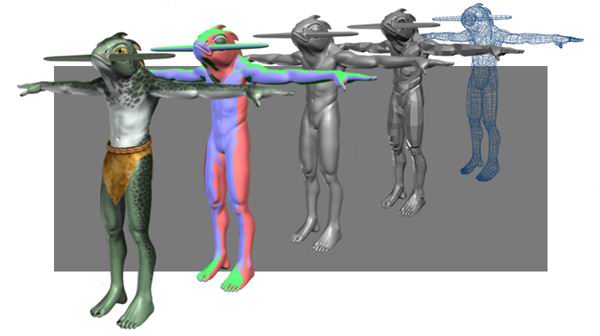
Example File: PrimitiveMan_Example_01.mb
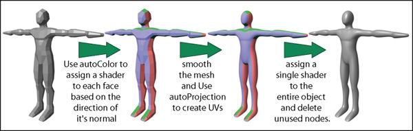
1. Run autoColor on the low res polygonal mesh. This will assign color coded shaders to the faces of the polygonal object. Each shader represents a projection. The color represents which direction the projection will come from. For example the Zpositive Shader is light blue. looking at the mesh an artist can quickly tell that the faces that are light blue will be projected from the front.
2. Edit the assignments of the faces to optimize the shells. At this point you should stop and look at the color of the faces in the mesh. Make sure that each face will be projected from the direction you want. If a face seems like it would be better off getting projected with a different shader group select that face and assign the other shader. Try to reduce the amount of seams that will occur. Remember that the autoColor script is intended to be used only as a starting point. The real decisions about direction should be made by you at this stage.
3. Run autoShellAssign to assign a separate shader to each shell of UVs that will be created. If you try smoothing the mesh and running autoProjection after step 2 you willl notice that 6 projections are created. You will have accurate UVs and little to no texture stretching. However You will also notice that the UVs for parts of your model will be overlapping. This will cause areas of the map to repeat. Reusing areas of your texture map by overlapping UVs is good if you mean to do it. That isn’t the case at this stage. We need to be able to move each shell of UVs created individualy so that we can move areas that overlap apart.
The MEL script autoShellAssign assigns a separate shader to each shell of UVs that will result from the projections we create. Because each of these shaders will eventually become a projection we will be able to use these projections to prevent overlapping UVs. Although this will not eliminate all overlapping it will eliminate the vast majority of the problem.
4. Combine any shells that can use the same projection without overlapping. Use the MEL script graphFaceMaterials to find the shaders on individual shells. Although autoShellAssign is useful to prevent overlapping it has a tendency for overkill. Not every shell on an object needs to have it’s own projection. In fact if it did we would quickly end up with an insane amount of history on our character. At this stage you should go back and use the graphFaceMaterials script to determine which shader is on each shell and try to combine as many of them as you can into as few shaders as possible.
5. Smooth the mesh to level two using the polySmoothFace node. Be sure to use the exponential smooth algorithm as the linear algorithm will not update the UVs correctly once they are projected. Note that the whatever smooth level the model is at when it is projected will be the maximum smooth level for the model. Usually the highest you will want to go is level 2.
6. Run autoProject to create projections based on the shaderGroup assignments. The autoproject script selects the faces contained in each ShaderGroup on the object one at a time and creates a projection onto those faces based on the name of the shader. For example the Z negative shader will be projected from the negative Z direction. Note that because the script works based on the names of the shaders you should not rename any of the shaders. Doing so may cause the script to fail.
7. Set the polySmoothFace.divisions attribute back to zero. Smooth level two is usually pretty heavy you will want to set the divisions attribute back down to zero while you move the projections apart.
8. Use the MEL scripts scrollUp scrollDown and selectProjection to select each projection individually and move them apart so that they no longer overlap. Use the projection size attribute to pack the shells in as tightly as possible. Depending on the complexity of your model and how careful you were when combining shaders during step 4 you should now have quite a few projections in the history of your mesh. The History of your object should have the polySmoothFace node first then the projections after it.
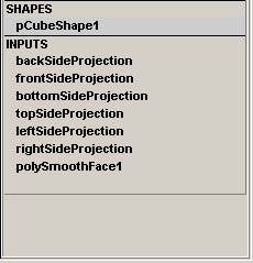
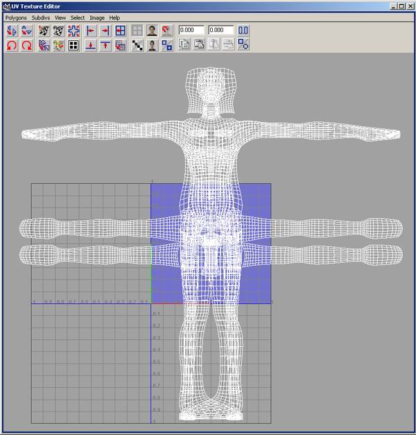
If you look in the UV texture editor you will see that the UVs for your mesh have been created. However because the Image center X and Y attributes of all the projections are set to 0.5 the projections are all piled up on top of each other. Also there is a good chance that the scale of each of the shells is either too big or too small for the UV texture space.
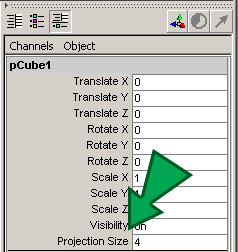
If you select your mesh and look in the channel box you will notice that a projection size attribute has been added underneath visibility. This attribute now controls the scale of all the projections created by autoProjection. By adjusting it up and down you can scale the UVs of the mesh to fit the UV texture editor. Keeping all the projections the same size will keep the scale of the UV shells proportional to each other. This will keep the scale of the texture map uniform across the entire surface of the mesh. It will also help reduce the appearance of texture seams.
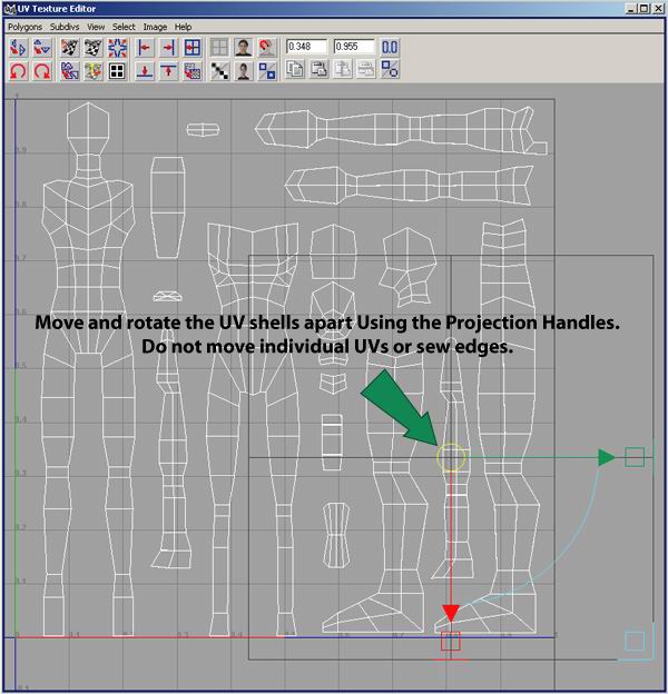
If you click on the first projection in the chain and hit the T key you will notice that the projection’s move handles will show up in the UV texture editor. Use these handles to move the projections apart so that their UVs no longer overlap. By using these handles to move the projections apart instead of selecting individual UVs we can ensure that this UV set will function on any smooth level. This is because by moving the projection handles we are actually moving the projection in relationship to the UV texture editor and not the UVs. Notice that no polyTweakUV nodes are added when you move these handles.
Attempt to pack the UV texture editor as tightly as possible. This will ensure that your texture maps have sufficient resolution.
Example File: PrimitiveMan_Example_02.mb
Do not select individual UVs and move them. Do not sew any edges. Do not hit Layout UVs. Doing so will cause your UV set to go totally wacky when you change the smooth level of the mesh.
Once you have the first projection selected you can use the scrollUp and scrollDown scripts to quickly select the next or the previous projection in history. I assign these scripts to hotkeys so I can scroll up and down quickly. I use Alt+1 for up and Alt+2 for down. ScrollUp selects the next Projection ScrollDown selects the previous one.
you can also use the selectProjection script to tell you which projection contains a specific face. Select a face on the shell you want to move and execute selectProjection. It’s corresponding projection will be selected. Again I assign this script to a hotkey, Alt+3, so I can get to it quicky.
9. Assign a single shader to the entire mesh at the object level. At this point you no longer need the shaders that are assigned to your mesh. You should save a separate scene file containing the mesh with these shaders just in case. Then create a single shader and assign it to the entire mesh. In the hypershade use the edit delete unused nodes command to get rid of the old autoColor shaders.
Example File: PrimitiveMan_Example_03.mb
Note that the selectProjection script only works while the autoColor shaders are still on the object. After you remove them you will have to either pick projections manually or use the scrollUp and scrollDown scripts.
10. Delete unused nodes.
Advantages and disadvantages of laying out UVs with autoColor.
Advantages.
1. Creates a UV set that automatically updates to match smooth level 0,1 and 2.
2. Color feedback allows artists to better visualize the end results of the projections.
3. UVs can be generated quickly allowing more time to be spent painting texture maps.
4. Produces an accurate 2D representation of a 3D object.
Disadvantages.
1. UVs cannot be selected and edited individually.
2. Shells cannot be sewn together to eliminate texture seams.
3. Require 3D paint software in order to be totally effective.
VII. Handing your model over to a character setup artist.
Production pipeline.
Having a production pipeline in place when you are creating smoothed polygonal characters can eliminate wasted time, speed up production and improve the quality of the finished model.
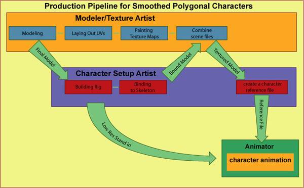
This is a generic production pipeline for creating smooth polygonal models. The goal is to have as many people working at the same time as possible to eliminate wasted time.
Note that the Modeler/Texture artist and the character setup artist are working at the same time. It is also sometimes possible to have the character setup artist provide the animators with a low res stand in for the character once the rig is built. This way the animators can start working while the setup artist is still setting weights and working out the deformations of the high res mesh.
Remember to clean up your scene files, name all nodes and group them into an organized structure. Delete any extraneous layers. Organization will save you headaches down the line.
Merging the UV reference file with the setup file.
![]()
In this proposed pipeline you will notice that the modeler/texture artist and the character setup artist are should be finishing their files at about the same time. Now it is time to merge the file containing the UVs and texture information with the file containing the character rig and skin weights. The resulting file can be cleaned up and organized then saved as a reference file which animators can have access to.
1. Clean up your file containing the UV reference All UV reference objects should be named and grouped together. Delete all layers and any extraneous geometry. Run file – optimize scene size.
3. Import the UV reference file into the setup file.
4. Move the UV reference group off to the side.
5. Transfer UVs from each UV reference object to its bound counterpart. Note that a single UV reference can be used for multiple objects. For example the right and left hand can use the same UV reference. Make sure the normals are facing the right direction.
6. Link all polygonal geometry to a control (generally the scale cube) using the MEL script smoothOperator. In order for the transfer to work correctly the UV reference and its skinned counterpart must be on the same smooth level. The MEL script smoothOperator changes the smooth level of all the geometry in a character and the UVreference at the same time. This ensures that the UV transfer always functions correctly when the characters smooth level changes.
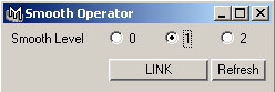
To use smoothOperator make sure that all the polygonal geometry in the character has a polySmoothFace node. Select all the polygonal geometry in the character and the UV reference then select any object to use as a smooth control. I usually use the scaleCube or parent of the rig. Hit the link button. the last object you had selected is now a control object for the smooth level of the entire character. Select the control obect by itself. click on the numbers in the smoothOperator window to set the value of all the polySmoothFace nodes on the character.
Hiding and locking the UV reference
It is important that you hide and lock as much of your work as possible. The best way to avoid having your coworkers accidentally set keyframes on or delete important objects out of the scene is to turn off the visibility and lock all the channels. Put all nodes into an organized file structure. Try to group all nodes for a character into one group and eliminate any extraneous layers. This will make working on a scene with multiple characters much easier.
Remember that if someone accidentally keys or deletes something that they shouldn’t have it is partially your fault for giving them access to that object in the first place.
1. Hide all UV reference objects and the UV reference group by turning off visibility.
2. Lock all channels
3. Make all channels non keyable.
4. Place the UV reference group in the do not delete group.
5. Try display-show all to make sure nothing shows up.
Special Thanks goes to Ted Forgrave for his assistance in developing this process and for writing the following scripts:
autoColor.mel
autoProjection.mel
deleteInput.mel
selectProjection.mel
smoothOperator.mel